At the mesoscopic scale, i.e. on distances r >> λc,
the substrate must be considered as deformable. Let us split the frictional area
into (rigid) blocks of size λc. In a general 3D model of
the elastic slider, the nth λ-block is
characterized by a coordinate Xn, and its dynamics is
described by the ME for the distribution functions Qn(un;
Xn). A solution of these MEs gives the interface forces
Fn(Xn). Then, the transition
from the discrete numbering of blocks to a continuum interface coordinate r
is trivial: n → r, Qn(un;
Xn) → Q[u; X(r); r],
Pn(u) → P(u; r),
Γn(Xn) →
Γ[X(r); r], Fn(Xn) →
F[X(r); r] (here r is a two-dimensional
vector at the interface), and the master equation now takes the
form:
| |
∂Q[u;
X(r); r]
∂X(r) |
+ |
∂Q[u;
X(r); r]
∂u |
+ P(u) Q[u;
X(r); r] = δ(u) Γ[X(r);
r] , |
|
(21) |
where we assumed that, for the sake of simplicity, the contacts are reborn with
zero stretching, R(u) = δ(u), and
| Γ[X(r); r]
= |
⌠
⌡
|
dξ P(ξ)
Q[ξ; X(r); r] . |
|
(22) |
Equations (21, 22) should be completed with the elastic equation of motion for
the sliding body (here we assume isotropic slider)
| |
d2u/dt2
+ η du/dt = G1∇2u
+ G2∇(∇·u ) , |
|
(23) |
where u(R) is the 3D displacement vector in the slider, R={x,y,z}, η
is the intrinsic damping in the slider, G1= E/2(1+ν)ρ
= ct2 and G2= G1/(1−2ν)
= cl2− ct2,
E, ν and ρ are the Young modulus, Poisson ratio
and mass density of the slider correspondingly, and cl
(ct) is the longitudinal (transverse) sound speed.
Equation (23) should be solved with corresponding boundary and initial
conditions. In particular, at the interface (the bottom plane of the slider,
where z=0 and {x,y}=r) we must have ux=
X(r), uy= uz= 0,
and the shear stress should equal F[X(r); r] /λc2,
where the friction force acting on the λ-block from the
interface,
| F[X(r);
r] = Nλkc
|
⌠
⌡
|
dξ ξ Q[ξ;
X(r); r] , |
|
(24) |
should be obtained from the solution of Eq.(21) [here Nλ=
(λc/a)2].
Equations (21−24) form the complete set of equations which describes evolution
of the tribological system; in a general case it has to be solved
numerically. However, a qualitative picture may be obtained analytically. The
interface dynamics depends on whether or not the λ-blocks
undergo the elastic instability, i.e., on the ratio of the stiffness of the λ-block
Kλ≈ (2cl2+ 3ct2)ρλc
[as follows from the discretized version of Eq.(23)]
and the effective critical stiffness parameter of the interface Kλ*eff
= β0Kλ*, where Kλ*~ Kλsxc/Δxs
and Kλs= Nλkc. If the elastic instability does not appear, then a
local perturbation at the interface relaxes, spreading over an area of size λs
− the screening length considered in next section. In the opposite case, when the
elastic instability does emerge (locally), in may propagate through the
interface. Below we consider a simplified one-dimensional version,
which allows us to get some analytical results (the using of the 1D model is also supported by the fact that the largest forces
near the broken contact are just ahead/behind it − see
Fig.I1).
Recall that the interaction between the λ-blocks is
weaker than in the short-range zone, it follows the law δf
∝ r–3
which determines, e.g., the block-block interaction strength κλ in Eq.(26) below (although the
interaction is power-law, we may consider the interaction of nearest neighbors only, because
excitations at the interface, such as "kinks", are localized
excitations, and the role of long-range character of the interaction reduces to
modification of their parameters).
Let us split the slider in λ-blocks
(rigid blocks) and consider the block-block interaction in a mean-field fashion. Due to sliding of
neighboring blocks, the force acting on the nth
λ-block gets an addition shift.
This effect may be accounted with the help of a substitution fn→ fn+
Δfn, Δfn= Σm≠n fm× Prob(m
→ broken) × Πmn≈ xcΣm≠n
fmΓmΠmn (recall that the sum is over
the λ-blocks here), or approximately
|
fn→
[ 1 + xcΣm≠n
Γm(Xm) Πmn
] fn
,
|
|
(25) |
where Γm(Xm)
= ∫du Pm(u) Qm(u; Xm) so that
NλΓm(Xm)
is the number of broken contacts in the mth λ-block
per its unit displacement, and
describes the dimensionless (i.e., normalized on fs)
elastic interaction between the λ-blocks separated by
the distance rmn. In this way the force is given by
fsΠ; the numerical constant κλ~
κa/λc depends on the substrate and interface
parameters.
Let us introduce the dimensionless variable εn= xcΣm≠n
Γm(Xm) Πmn.
The shift of forces in the nth block due to broken contacts in the
neighboring blocks may be accounted by a renormalization of the rate:
| Pn(u)
→ Pn [ (1+εn)
u ] . |
|
(27) |
Indeed, when contacts in the neighboring blocks break, then the forces in the
given block increase, εn> 0, and
the contacts in the given block should start to break earlier, i.e., their
threshold distribution effectively shifts to lower values.
Making the transition from the discrete sliding blocks to a continuum sliding
interface, Πmn→ Π(r'−r) and εn→ ε(r), we obtain a master equation of the form:
| |
∂Q[u;
X(r); r]
∂X(r) |
+ |
∂Q[u;
X(r); r]
∂u |
+ P([1+ε(r)] u) Q[u; X(r); r] =
δ(u) Γ[X(r);
r] , |
|
(28) |
where we again assumed that the contacts are reborn with zero stretchings, R(u)
= δ(u),
| ε(r)
= xcλc–2 |
⌠
⌡ |
|r'-r|
≥ λc |
d2r' Γ[X(r');
r'] Π(r'−r)
|
|
(29) |
and
| Γ[X(r);
r] = |
⌠
⌡ |
dξ P(
[1+ε(r)]
ξ ) Q[ξ; X(r); r]
. |
|
(30) |
In the long-wave limit, when |dε(r)/dr|
<< ε(r)/λc,
we may assume that the interface is locally equilibrated, i.e., the distribution
of forces on contacts is close to the steady-state solution of the master
equation, Q[u; X(r); r] ≈
Qs(u; r), which depends parametrically
on the coordinate r through the function ε(r)
entered into the expression for the rate P( [(1+ε(r)]
u ). The stationary solution of the ME is known
analytically, thus we
may find the function (30),
Γ(r) = [1 + ε(r)]/xc.
Together with Eq.(29)
this gives a self-consistent equation on the function ε(r):
| ε(r)
= λc–2 |
⌠
⌡ |
|r'-r|
≥ λc |
d2r' [(1+ε(r')]
Π(r'−r)
. |
|
(31) |
Taking into account the interaction of nearest neighboring λ-blocks
only and expanding ε(r) in Taylor series, we
obtain the equation
| ε(r)
= Π0 [ 1 + ε(r)
+ 1/2 λc2ε"(r)
] , |
|
(32) |
where Π0= νΠ(λc)
= νNλκλ~ νκλc/a and ν = 2 − 4 is
the number of nearest neighbors. Writing ε(r)
= ε0+ Δε(r),
where ε0= Π0/(1−Π0), Eq.(32)
may be rewritten as
where λs= λc(ε0/2)1/2 is the characteristic screening length in the sliding
interface.
From the known analytical solution of the ME for the steady state, we may predict
the dependence of screening length on temperature and the sliding velocity v. In
particular, if T > 0, then λs∝ v–1/2→
∞ when v
→ 0.
In the frictional interface, sliding begins at some weak place and then
expands throughout the interface. Such a situation is close to the one known in
fracture mechanics as the mode II crack, when the shear is applied along the
fracture plane. In friction problem, however, the crack first opens, evolves (propagates, grows,
extends) during some "delay" time τ, but then it
either expands throughout the whole interface, or it will close because
of the load. Below we consider the latter scenario, when one solid slips over
another due to motion of the so-called self-healing crack − a wave or
"bubble" of separation moving like a crease on rug. Our plan is to use
ideas from fracture mechanics, adapt them to the friction problem and then
reduce it to the Frenkel-Kontorova (FK) model in order to describe collective
motion of contacts in the frictional interface.
 |
 |
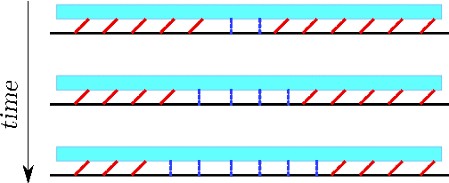
| Figure 0: Left: Schematic picture showing the propagation of the
friction fronts generated at weak points in the center of the system.
The thick (red) lines represent λ-contacts which have been
stretched by the shear. The (blue) dotted lines represent λ-contacts
which have relaxed by sliding. As time grows the relaxed region extends
and its boundaries make two kinks separating domains where the λ-contacts
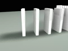
are in different states. Right: domino effect. |
When one of the "collective contacts" (the λ-contact)
breaks, it may initiate a chain reaction, with contacts breaking domino-like one
after another. This scenario may be described accurately by reducing the system
of contacts to a FK-like model. Recall that the
FK model
describes a chain of harmonically interacting atoms subjected to the external
periodic potential Vsub(x)
of the substrate. If the atoms are additionally driven by an external force f, then the equations of motion for the atomic coordinates un
take the form
| m d2un/dt2
+ mη dun/dt −
g (un+1+ un-1−
2un) + V 'sub(un) = f , |
|
where m is the atomic mass, g is the strength of elastic
interaction between the atoms, and η is an effective
damping coefficient which describes dissipation phenomena such as the excitation
of phonons in the substrate. The main advantage of using the FK
model is that its dynamics is well known. Mass transport along the chain
is carried by kinks (antikinks) − local compressions (extensions) of otherwise
commensurate structure. The kink is a well-defined topologically stable
excitation (quasiparticle) characterized by an effective mass mk
which depends on the kink velocity vk, mk= mk0(1−vk2/c2)–1/2 (the
relativistic Lorentz contraction of the kink width when its velocity approaches
the sound speed c). Therefore, the maximal kink velocity is vk
max= c. In the discrete chain, kinks
move in the so-called Peierls-Nabarro (PN) potential, whose amplitude is much
lower than that of the primary potential Vsub(x). Therefore, the kink motion is activated over these barriers, and its
average
minimal velocity vk min is
nonzero. The steady-state kink motion is determined by the energy balance: the
incoming energy (because of action of the external driving force f)
should go to creation of new "surfaces" (determined by the amplitude of the
substrate potential) plus excitation of phonons by the moving kink (described by
the phenomenological damping coefficient η), so that
vk(f) = f /(mkη).
FK-like model. Thus, let us consider a chain of λ-contacts ("atoms" of mass m
= ρλc3), coupled
harmonically with an elastic constant g, driven externally through a
spring of elastic constant K with the spring's end moving with a velocity v.
Using the discretized version of Eq.(23),
the elastic constants may be estimated as g ≈
2Eλc(1−ν)/[(1−2ν)(1+ν)] and K ≈ λcρct2. The
λ-contacts are coupled
"frictionally" with the bottom substrate; the latter is described by the
nonlinear force Fs(u). The equation of motion
of the discrete chain is
| m d2un/dt2
+ mη dun/dt − g (un+1+ un-1−
2un) + Fs(un) + Kun
= f(t) , |
|
(34) |
where the driving force is given by f(t) = Kvt.
The substrate force Fs(u) is to be found from the
solution of the ME for the rigid λ-block.
A typical evolution of the chain is shown in Fig.6.
|
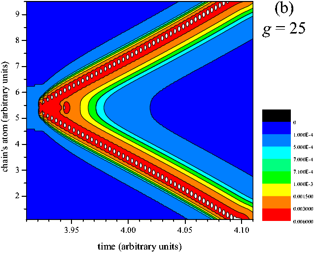 |
Figure 6: Color map of atomic
velocities for a typical evolution of the chain of contacts. The nearest
neighboring contacts interact elastically with the constant g = 25.
The interaction with the substrate is modeled by the function
Fs(u) = kc [tanh(u) + 1.5e-usin(3u)]
with kc= 1 defined for 0 ≤ u < uc= 1 and periodically prolonged for other values of u. All contacts
are driven through the springs of the elastic constant K = 0.07,
their ends moving with the velocity v = 10–4.
The motion is overdamped (m = 1, η = 100). To initiate the breaking, two central contacts interact with the
substrate with smaller values of the elastic constant, kc= 0.5.
|
The general case may be investigated numerically only. Let us first consider a
simplified case, when Fs(u) has the sawtooth
shape, i.e. it is defined as
| Fs(u)
= kcu for
0 ≤ u < uc |
|
(35) |
and periodically prolonged for other values of u. We assume that f
is approximately constant during kink motion (otherwise, the kink will
accelerate during its motion along the chain); this is true if the change of
the driving force Δf = Kv Δt
during kink motion through the chain, Δt =
L/vk (L is the chain length and vk
is kink velocity), is much lower than kcuc,
or K/kc << (vk/v)(uc/L).
Let us define the function F(u) =
Fs(u) + Ku −
f. The degenerated ground states of the chain are determined by the
equation F(u) = 0. Let the
right-hand side (n →
∞)
of the chain be unrelaxed, kcuR
+ KuR = f, or
while the left-hand side (n → −∞) already undergone relaxation, kc(uL− uc)
+ KuL = f, or
| uL =
(f + kcuc) / (kc+ K)
. |
|
(37) |
Thus, the FK-like model of friction (the FK-ME model) is described by Eqs.(34)
and (35) with the
boundary conditions given by Eqs.(36)
and (37).
|
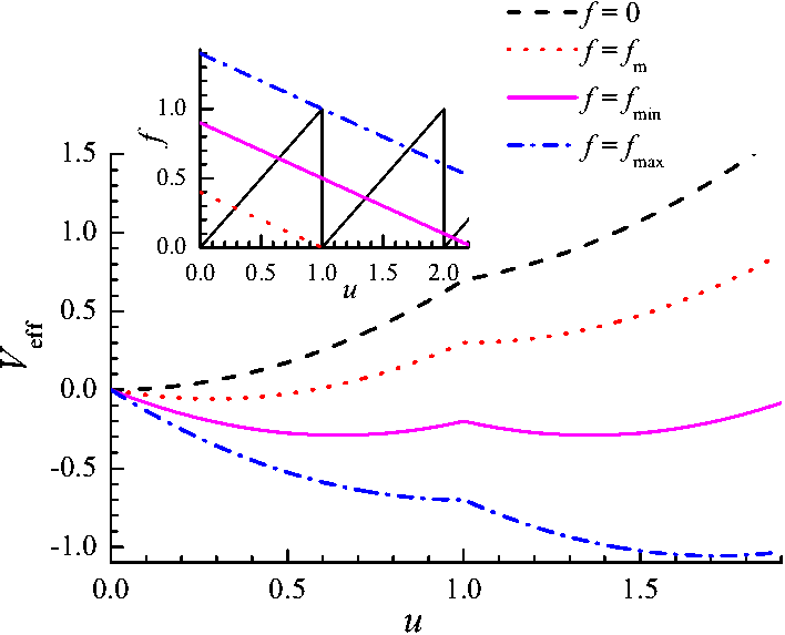 |
Figure 6a: The effective FK-like
"potential" Veff(u)
= ∫du F(u)
for uc= 1, k = 1, K = 0.4 and different values of the driving force: f = 0 (dashed, no driving), f
= fm= Kuc (red
dotted, when
the second local minimum appears), f = fmin=
(0.5k+K )uc (solid magenta, the two local minima
are characterized by the same energy), and f = fmax=
(k+K)uc (blue das-dotted, the left minimum
disappears). Inset shows graphical solution of the equation
F(u) = 0, or F(u)
= f − Ku.
|
Continuum-limit approximation. Let the system be overdamped (d2u/dt2=0);
later on we shall remove this restriction. In the continuum-limit approximation,
n → x=na (a=1), the
motion equation takes the form
| mηut −
a2guxx+
F(u) = 0, F(u)|x
→ ±∞
= 0 . |
|
(38) |
We look for a solution in the form of a wave of stationary profile (the solitary
wave), u(x,t) = u(x−vkt), so that ut= −vku' and uxx= u".
In this case Eq.(38)
takes the form
which may be solved analytically by standard methods.
A solution of Eq.(39)
with these boundary conditions exists only for a certain value of the kink
velocity vk, defined by the equation
| (mηvk)2 = ga2(kc+ K)(2−β)2/(β−1)
, |
|
(40) |
where β = kc/(k*−K) and k* = f/uc.
The solitary-wave solution exists for forces fmin< f < fmax only. The minimal
force which supports the kink motion − the Griffith threshold − is given by
The maximal force, for which a kink may exist, is given by
at higher forces, the barriers of Fs(u) are
degraded, the stationary ground states disappear, and the whole chain must
switch to the sliding state.
From Eq.(40) we can
find the kink velocity as a function of the driving force. At low velocities
where we introduced the effective kink (crack) mass
while at f → fmax
the velocity tends to infinity,
| mηvk ≈
|
√ |
| gkc(kc+ K) a2uc
(fmax− f) |
|
. |
|
(45) |
The latter limit should be corrected by taking into account inertia effects. The
term md2u/dt2 in Eq.(34)
gives mvk2u" for the solitary-wave
solution, so it can be incorporated if we substitute in the above equations g
→ geff =
g (1 − vk2/c02), where c0= (ga2/m)1/2 is
the sound speed along the chain. The high-velocity limit now takes the form
| vk
≈ c0 |
/ |
|
√ |
| 1 + |
mη2 (fmax− f)
kc (kc+ K) uc |
|
. |
|
(46) |
Simulation. The continuum-limit approximate is
accurate for the case of strong interaction between the contacts, g >> 1;
in the opposite limit one has to resort to computer simulation. We solved Eq.(34)
by the Runge-Kutta method. As the initial state, we took the chain of length
N (typically N = 3×10³ or 3×10⁴) with periodic
boundary conditions and all contacts relaxed, but the threshold breaking value
for two central contacts was taken lower than for the other contacts. Then the
driving force increases because of stage motion, two central contacts break
first and initiate two solitary waves of subsequent contact breaking which
propagate in the opposite directions through the chain. The value kc'
of the lower threshold of the central contacts determines the driving force and
therefore the kink velocity; the lower this threshold, the lower the threshold
force for the motion to start. As soon as the kink motion is initiated, the
kc values of the central contacts are restored to the
same value as for other contacts (otherwise these contacts will act as a source
of creation of new and new pairs of kinks), and we change the stage motion to in the
opposite direction, v > 0 → vb< 0, so that the driving force linearly decreases with time (see Fig.7b)
and
the average chain velocity <dui/dt> = N–1Σidui/dt
decreases as well (Fig.7c)
until the motion stops (Fig.7a).
|
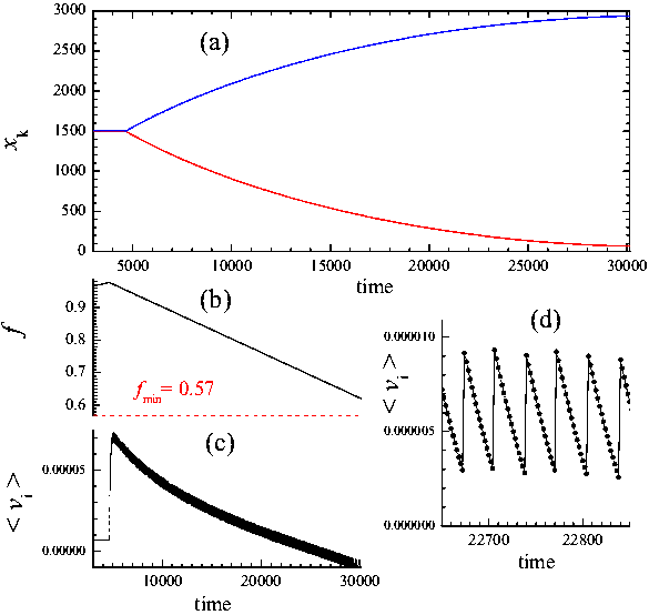 |
Figure 7: Evolution of the
chain of N = 3000 contacts. The nearest neighboring contacts
interact elastically with the constant g = 25, the interaction with
the substrate is modeled by the sawtooth function (35)
with kc= 1 and uc= 1. All contacts are driven through the springs of elastic constant
K = 0.07, their ends moving with the velocity v = 10–4.
The motion is overdamped (m = 1, η = 100). To initiate the breaking, two central contacts interact with the
substrate with smaller spring constants, kc'= 0.5.
When the kinks motion begins, the elastic constants of the central
contacts restore their values to kc= 1, and the driving velocity changes its sign, v →
vb= −2×10⁻⁴.
(a) shows the kinks centers (defined as places where the
contact velocity
is maximal),
(b) shows the driving force f(t),
(c) shows
the average chain velocity <dui/dt> = N–1Σidui/dt,
and
(d) demonstrates oscillation of the velocity due to PN barriers.
|
Also, such an algorithm
allows us to find the dependence of the kink velocity determined as
| vk =
nk–1N
(<dui/dt> − v)
, |
|
(47) |
where nk= 2 is the number of moving kinks in the chain
and v = [du/dt]L,R= vbK/(kc+ K) is the background velocity, on the driving force f. These
dependences are presented in Fig.8;
they agree well with that predicted by Eqs.(40)
and (43).
|
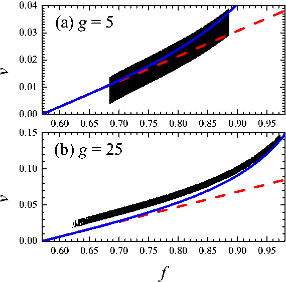 |
Figure 8: Kink velocity
versus the driving force for
(a) g=5 (vb= −4×10⁻⁵)
and (b) g=25 (vb= −2×10⁻⁴);
N = 3×10⁴,
other parameters as in Fig.7.
Blue solid and red dashed lines correspond to Eqs.(40)
and (43),
correspondingly. |
Contrary to the continuum-limit
approximation, in the discrete chain of contacts the kink oscillates during
motion (see Fig.7d) −
the well-known discreteness effect of the FK model due to existence of the PN
barriers. The stronger the
elastic interaction between the contacts, the larger the kink "width" and the
smaller the kink oscillations (compare Figs.8a
and 8b). The amplitude of oscillations also depends on the shape of the
"substrate potential" − it
is larger for a sawtooth potential Fs(u), but
smaller for a smoother shapes. Recall that the λ-contacts
are characterized by a smooth dependence Fs(u)
as follows from the solution of the ME (for example, see
 ). The PN oscillations determine the lowest
average kink velocity. Therefore, the lowest velocity allowed for the frictional
crack propagation, vk min,
is determined by the parameters g and λc
− the larger are g and λc,
the smaller is vk min.
). The PN oscillations determine the lowest
average kink velocity. Therefore, the lowest velocity allowed for the frictional
crack propagation, vk min,
is determined by the parameters g and λc
− the larger are g and λc,
the smaller is vk min.
Discussion. The FK-ME model used here is
rather close to the well-known 1D Burridge-Knopoff (BK) model of earthquakes
with a velocity-weakening friction law. The difference is in the interface
force Fs(u): we use the function derived from
the ME-EQ model (with well-defined parameters which may be extracted from
experiments or calculated from first principles), whereas the BK model adopts a
phenomenological velocity-dependent function for Fs.
Nevertheless, the qualitative behavior of the two models is similar, the BK
model also exhibits solitary-wave dynamics as was demonstrated numerically by
Schmittbuhl et.al. [Schmittbuhl J., Vilotte J.-P. and Roux S.: Propagative
Macrodislocation Modes in an Earthquake Fault Model. Europhys. Lett. 21,
375-380 (1993)]. In our case, however, by reducing the model to the FK-ME one, we can
describe the solitary waves analytically.
In the simulation we started from the well-defined initial configuration, when
all contacts are relaxed except the one or two where kink's motion is initiated.
If one starts from a random initial configuration, we expect that kinks will
emerge at random places and several kinks may propagate through the system
simultaneously.
Also we assumed that all λ-contacts
are characterized by the same Fs(u) dependence
and thus have the same threshold values Fth.
This is correct if the number of original contacts within a single
λ-contact, Nλ= (λc/ac)2, is infinite. Otherwise, different λ-contacts
will have different threshold values, although the
distribution of the thresholds is narrower that the distribution of thresholds
of single asperities by a factor √Nλ.
A narrow distribution of thresholds will nevertheless have a qualitative effect
because rupture fronts may stop when they meet a λ-contact
with a threshold above the driving force.
Our approach may also incorporate the existence of disorder and defects always
present in real materials. On the one hand, defects may nucleate kinks (cracks);
on the other hand, the kink propagation may be slowed down up to its complete
arrest due to pinning by the defects.
Thus, reducing the EQ-ME model of friction to the FK-ME one, we described
analytically
avalanche-like dynamics of the frictional interface − the solitary wave of
contacts breaking. The analogy with the FK model may be extended
even further: (i) Effects of nonzero temperature may be considered; at T > 0 the sliding kinks will experience an
additional damping, while the immobile (arrested) kinks will slowly move (creep)
due to thermally activated jumps; (ii) As was
shown, a fast driven kink begins to
oscillate due to excitation of its shape mode, and then, with the further
increase of driving, the kink is destroyed; this effect is similar to what is
observed in fracture mechanics, where cracks begin to oscillate and then
branch; (iii) One may suppose that the damping coefficient
η in the equation of motion (34)
depends on the kink velocity, η(v); in
fracture mechanics, this coefficient defines the rate at which the energy is
removed from the crack edge, thus it plays a crucial role.
Published in: O.M. Braun and M. Peyrard, Phys. Rev. E 85 (2012) 026111
"Crack in the frictional interface as a solitary wave"
Recent experiments allowed visualization of
the onset of sliding in a variety of experimental situations. These experiments have revealed that
the onset of sliding is always mediated by the propagation of micro-slip (rupture) fronts,
called precursors, which separate a stuck region and a slipping region along the contact interface.
In side-driven plane-on-plane contacts, the precursors were nucleated
near the trailing edge of the contact, where the loading is applied. The first
precursor propagates through the shear and normal stress fields produced by the
initial loading of the system only. After the precursor has stopped, the
mechanical state of the interface is modified all along the ruptured path, so
that the next fronts propagate through the stress field prepared by the
previous ones.
Several models have
been proposed to investigate the series of precursors to sliding.
Braun et al. (2009) used dynamic simulation in which the slider was
modeled as a chain of blocks
coupled by springs, while the interface was treated as a set of "frictional"
springs with random breaking thresholds. They reproduced both a series of
precursors and a modification of the stress field by the
precursors as observed at experiments. These results stimulated the study of
different simplified models. In these models the interface was described by the
phenomenological Amontons-Coulomb law of
friction: the interface is pinned until the local ratio of shear to normal
stress reaches the static friction coefficient μs,
and then the interface is locally slipping and characterized by a kinetic friction
coefficient μk<
μs. All these models produce a series
of precursors nucleated at the trailing edge. Maegawa et al. (2010) further showed that an asymmetric normal loading influences the precursor
length. Scheibert and Dysthe (2010) showed that a similar effect is obtained for a symmetric normal loading, as soon
as the friction force is not applied exactly in the plane of the contact
interface. Amundsen et al. (2012) showed that, to be realistic, 1D models should involve an intrinsic length scale
for the interfacial stress variations. Trømborg et al. (2011) showed that, in 2D models, such a length scale naturally arises when introducing
the system's boundary conditions and bulk elasticity. In all the above simplified models, each broken contact point repins
when its slipping velocity goes back to zero. As a consequence, the
precursor front separates a stick region from a region which is slipping behind it.
Above, however, we developed the multiscale
model of the frictional interface that does not use the phenomenological Amontons-Coulomb friction law: the friction between two solids results from multiple individual micro-junctions
which break under stress and form again elsewhere. As a consequence,
the rupture mode of the interface corresponds to the self-healing crack, i.e. the
slipping part of the interface is confined between the rupture front and a
repinning front; such cracks may be treated as solitary aves. In the
previous section we used a too simplified 1D model of the
self-healing crack propagation: first, we postulated the elastic interaction
between the nearest neighboring contacts, and second, we assumed the uniform
constant driving force acting on the contacts. Both these issues, however, are
produced by the elastic body of the slider. A full treatment of the problem
requires a solution of Eqs.(21−24) which
can be done numerically only. Below we propose a more involved 1D model, where
the slider elastic body is modeled as an additional 1D chain of blocks.
This model, being still oversimplified, nevertheless allows a rigorous
analytical treatment, describes the kinematics of the onset of sliding and
predicts the propagation length Λ of the first precursor as well as the shear
stress field associated with it.
1D model of elastic slider. We consider that
the macroscopic contact is made of a large number of micro-junctions in parallel,
with an average distance ac. Let an individual junction
(micro-contact, bridge, solid island, etc.) have an average elastic constant kc. Elastic theory introduces
the elastic correlation length λc
below which the frictional interface behaves
rigidly. The set of Nc= λc2/ac2
contacts within the area λc2 forms an effective macro-contact (the
λ-contact introduced above) with the elastic constant
k = Nckc. The λ-contacts are elastically coupled through the
deformation of the slider's bulk. If we denote by ui
the displacement of the point on the slider's bottom to which the ith λ-contact
is attached, then the elastic energy stored between two nearest neighboring λ-contacts
i and j in a non-uniformly deformed slider may formally be written
as (1/2)K (ui− uj)2,
where K is the slider rigidity defined below.
|
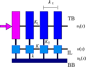 |
Figure J1: Sketch of the
model. The top block (TB, dark blue) is split into rigid blocks of size λc×W×H
connected by springs of elastic constant KL.
The position of the leftmost block (pink) is imposed by the pushing
device, ut(0,t) = vdt.
The interface layer (IL, light blue) is split in rigid blocks of size λc×W×λc
connected by springs of elastic constant K. The TB and IL blocks
are coupled by springs of elastic constant KT.
The IL is connected with the rigid bottom block (BB) by "frictional"
springs of elastic constant k.
|
Let us consider a one-dimensional (1D) model of the interface, treating it as a
chain of λ-contacts sandwiched between two macroscopic blocks (Fig.J1). The
top block (TB) of length L is elastic with the rigidity
K = EHW/L, where E is
the Young modulus of the slider, H is
the slider height (thickness) and W is its width (in our 1D model we have
to put W = λc in what follows), while the bottom
block (BB) is rigid for the sake of simplicity. Note that in this 1D model H
should be interpreted as some effective height where the driving force is
applied. Let us formally split the TB into N >> 1 rigid blocks of size λc
(N = L/λc). These
blocks are coupled by springs of elastic constant
| KL =
NK = EH =
E λc(H/λc)
. |
|
(J1) |
We consider the contact between the TB and BB as some interface layer (IL) of
thickness Hc~ λc
consisting of N λ-contacts coupled
by springs of elastic constant
The IL and TB are coupled elastically with the transverse rigidity
KT = [E/2(1+ν)]
(LW/H) (ν is the slider's Poisson's
ratio) which we model by N (transverse) springs of elastic constant
| KT =
|
KT
N |
= |
E λc
2(1+ν) |
|
λc
H |
. |
|
(J3) |
The IL is coupled "frictionally" with the top surface of the BB through springs
of elastic constant k (the stiffness of the λ-contacts). The
interface is stiff if k ~ K
and soft when k << K; we concentrate on the latter case which
corresponds to most experimental situations.
The system can be described by three variables: ut(x)
describes the displacement field of the TB, u(x) is the
displacement field of the blocks in the IL, and ub(x)
is the displacement of attachment points of the IL to the BB. The stress in the
IL is then given by
| σc(x) = k
[ u(x) − ub(x)
] /λc2
, |
|
(J4) |
while the "driving" stress is equal to
| σd(x) = KT
[ ut(x)
− u(x) ] /λc2
. |
|
(J5) |
Self-healing crack-like rupture. The frictional behaviour
of each junction connecting the IL to the BB is the following: it acts as a
spring of elastic constant k as long as its stretching remains below a
critical value us= fs/k
but breaks and then repines with zero stretching when the local shear
stress reaches σs= fs/λc2.
When a loading is applied to the slider, it is transmitted to each λ-contact due
to elasticity of the slider. The leftmost λ-contact
is the first to reach its breaking threshold, slide and locally relax the
interface. This causes an extra stress on the neighboring contacts, which tend
to slide too, so that sliding events propagate as a kink, extending the initial
relaxed domain. Such a scenario may be described as a propagation of the solitary wave,
i.e., the rupture mode corresponds to the self-healing
crack with crack's width equal to the lateral size of one contact λc.
In order to simplify the analysis, we suppose the existence of a hierarchy of
times: we assume that the pushing rate is adiabatically slow, vd→
0, while the sound speed (which determines the rate of propagation of the
elastic stress) is very large, vR→
∞. Therefore, when a front propagates, it is accompanied by a quasi-static
stress field defined by mechanical equilibrium of the forces acting on the
interface layer (thus, inertia effects are ignored here). In the following, we show that
there exist a typical length scale Λ which
characterizes the stress accumulation and thus the precursor propagation length.
Equations. In the discrete model we have x = iλc,
ut(x) → ut,i ,
u(x) → ui and ub(x) →
ubi. In equilibrium, the displacements should satisfy
| KL (ut,i+1+
ut,i-1−
2ut,i) = KT
(ut,i− ui)
, |
|
(J6) |
| K (ui+1+
ui-1−
2ui) = k (ui−
ubi) + KT (ui−
ut,i) . |
|
(J7) |
In the continuum approximation, these equations reduce to the set of equations:
| ut''(x)
= κT2 [ ut(x) −
u(x) ] , |
|
(J8) |
| u''(x) = κ2
[ u(x) − w(x) ] , |
|
(J9) |
| w(x) = β ut(x)
+ (1−β) ub(x)
, |
|
(J10) |
where κT = (KT /KL)1/2/λc,
κ = [(k + KT)/K]1/2/λc
and β = KT /(KT +
k).
A key trick of our analytical approach is that the general solution of the
equation u''(x) = κ2[u(x) − w(x)] is u(x) = De±κx − κ ∫xdξ w(ξ)
sinh[κ(x −
ξ)].
As we impose the position of the left-hand side (trailing edge) of the TB we
have
while the left-hand side of the IL is free so that
| K λcu'(0) + KT [Ut−
u(0)] = k [u(0) − ub(0)] . |
|
(J12) |
To simplify analytical consideration, we ignore the right-hand side boundary conditions
assuming that the chain is infinite, L→
∞,
so that ut(∞) = u(∞)
= ub(∞) = 0.
Let initially, at t=0, the system be completely relaxed: ut(x)
= u(x) = 0 and ub(x) = ub(0)(x)
= 0. We then start to push slowly the trailing edge of the TB, so that Ut=vdt
with vd→ 0. The solution of Eqs.(J8−J12) is:
| ut(x)
= D10e–κ1x + D20e–κ2x , |
|
(J13) |
| u(x) =
α1D10e–κ1x + α2D20e–κ2x , |
|
(J14) |
where
| κ1,22 =
|
1
2 |
|
[ |
(κ2 + κT2)
± |
√
|
D
|
|
] |
, |
|
(J15) |
| α1,2
= |
1
2 |
|
[ |
1 −
( κ2 ± |
√ |
D
|
) / κT2
|
] |
, |
|
(J16) |
| D
= (κ2 − κT2)2
+ 4βκ2κT2
, |
|
(J17) |
| D10 = (α2Ut − uc)
/ (α2−
α1) , |
|
(J18) |
| D20 = (uc−
α1Ut)
/ (α2−
α1) , |
|
(J19) |
and
| uc =
Ut |
| λc β κ2
(κ1− κ2) + (KT
/K) |
√ |
D
|
| λcκT2 (α2κ2− α1κ1) + λc2κ2
|
√ |
D
|
|
. |
|
(J20) |
The positions Ut and uc grow
together until the trailing edge of the TB reaches a position Ut0
where the left end of the IL achieves the threshold value us
at some time t1= Ut0/vd.
At t = t1 the left-most λ-contact breaks and
attaches again with zero stretching, ub(0) = ub(1)(0)
= us, and the whole system relaxes, adjusting itself to
a new configuration with ut(0) = Ut0,
ub(0) = us and ub(x
≥ λc) = 0. After relaxation,
all contacts have shifted to the right, so that the IL stress
σc(x) for x
≥ λc increases. As a
consequence, the stress on the second contact has grown above the threshold σs so that it must break too. This
domino-like process will continue until the stress at some (s0th)
contact will remain below the threshold. This first passage distance defines a
characteristic length Λ = s0λc
which controls the kinematics of the onset of sliding.
We emphasize that the driving stress σd(x),
Eq.(J5), changes
self-consistently during crack propagation, as u(x) changes. The
moving self-healing crack leaves behind itself relaxed contacts. When the crack
reaches a position s, the current shapes of the displacement fields
ut(x; s) and u(x; s) are given by
solution of Eqs.(J8−J10). The current displacement of the bottom surface of the IL, ub(x; s), is determined by the current propagation length of the
crack:
| ub(x; s) = u(x+0; x) for
x < s , |
|
(J21) |
while ahead the moving crack the contacts are still loaded,
| |
|
|
ub(x; s) = ub(0)(x)
for x > s . |
|
(J22) |
With these conditions, the functions ut(x;
s) and u(x; s) take the following form. For
the crack tail (x < s):
| ut(x; s) = [ D11(s)
sinh(κ1x) + D12(s)
cosh(κ1x) ] + [ D21(s)
sinh(κ2x) + D22(s)
cosh(κ2x) ] + |
ut(0; x)
, |
|
(J23) |
| u(x; s) =
α1[ D11(s)
sinh(κ1x) + D12(s)
cosh(κ1x) ] + α2[ D21(s) sinh(κ2x) +
D22(s) cosh(κ2x) ] +
u(0; x) ,
|
|
(J24) |
where
| ut(x0; x)
= |
⌠
⌡ |
x
x0 |
|
dξ ub(ξ)
{ b1sinh[κ1(x −
ξ)] + b2sinh[κ2(x −
ξ)] } , |
|
(J25) |
| u(x0; x)
= |
⌠
⌡ |
x
x0 |
|
dξ ub(ξ)
{ α1b1sinh[κ1(x −
ξ)] + α2b2sinh[κ2(x −
ξ)]
} , |
|
(J26) |
with b1= (1−β) κ2/κ1(α2− α1)
and b2= − b1κ1/κ2.
Ahead of the crack (x > s):
| ut(x; s) = D1(s)
e–κ1(x–s) + D2(s)
e–κ2(x–s) + ut(s; x)
, |
|
|
(J27) |
| u(x; s) = α1D1(s)
e–κ1(x–s) +
α2D2(s) e–κ2(x–s) + u(s; x)
. |
|
(J28) |
The coefficients D1(s), D2(s),
D11(s), D12(s), D21(s)
and D22(s) in Eqs.(J23−J28) are functionals of the function ub(0)(x)
and should be determined by the two left-hand-side boundary conditions (J11)
and (J12) and the
following four continuity conditions at x = s ± 0:
| ut(s − 0; s)
= ut(s + 0; s) , |
|
|
(J29) |
| ut'(s − 0; s)
= ut'(s + 0; s) , |
|
|
(J30) |
| u(s − 0; s)
= u(s + 0; s) , |
|
(J31) |
| u'(s − 0; s)
= u'(s + 0; s) , |
|
|
(J32) |
which finally lead to a set of integral equations that has to be solved
self-consistently.
Numerics. A typical solution of the equations for the
first crack passage, for a completely relaxed IL initially (ub(0)(x) = 0), is shown in Fig.J2.
|
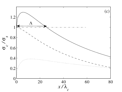 |
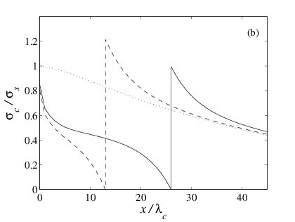
Figure J2:
(a) Displacement fields ut(x;
s) and u(x; s): when the crack nucleates
at t = t1 (s = 0, dotted, ut(x,0) = Ut0e–κ2x)
and during crack propagation for the distances s = 13λc
(dashed) and s = 26λc (full precursor length, solid curve).
(b) Stress field in the IL during crack propagation.
(c) Dashed line: shear stress in the IL at crack nucleation (t = t1−0). Solid line: shear stress in the IL, at the crack tip, when it passes at
location x (s = x) during its propagation. Dotted
line: extra stress Δσc(s).
H/λc = 25, k/K
= 0.03, ν = 0.3, L = 100λc. |
When the slider's height is much larger than λc, the displacement field in the
TB is approximately unchanged upon propagation of the crack, even if the
displacement in the IL almost double upon crack propagation (Fig.J2a).
Because the λ-contacts repin immediately after
breaking, they also immediately start to load again as the next λ-contacts relax and the
crack propagates. As a
consequence, the stress behind the crack is increasing with the distance to the
crack (Fig.J2b). Ahead
of the crack, the relaxed λ-contacts induce an extra
loading of the unbroken contacts ahead of the crack, characterized by a stress
peak at the crack location (Fig.J2b).
This extra stress Δσc is enough to
bring initially less stressed contacts up to their threshold. However, because
the initial stress is a decaying function of x, the extra stress is
sufficient to bring the contacts above their threshold only over a finite length Λ (Fig.J2c).
Analytics. For the first precursor arising from a
completely relaxed IL (ub(0)(x) = 0),
we found some analytical results. The full proof is available in
SI; here we will only
provide the main result and the assumptions made to get it.
We assume that the elastic correlation length is much smaller than the slider's
thickness (λc<< H). Since λc
is typically in the micrometer range, this assumption is valid for a large range
of tribological systems. We also assume that the interfacial stiffness is much
smaller than the internal stiffness of the slider (k << K). For
rough interfaces, this assumption is also generally true. Based on the results
of Fig.J2a, we assume that the displacement field in the TB is given by ut(x) ≈
Ut0e–κ2x
and does not change during crack propagation. Under these assumptions, we find
an analytical expression for the length Λ of the first precursor (see Eq.(41)
in
SI). This expression approximates, for Λ >> κ–1
(i.e., for large H/λc and/or for large k/K),
to
| Λ ≈ κ2–1
ln{ 2 / [(1 + β −
2κ2/κ) Ψ1] } , |
|
(J33) |
where Ψ1= 1 + λcκ2 /(1 + λcκ)
.
  |
|
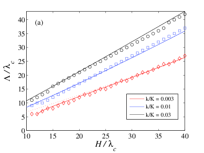
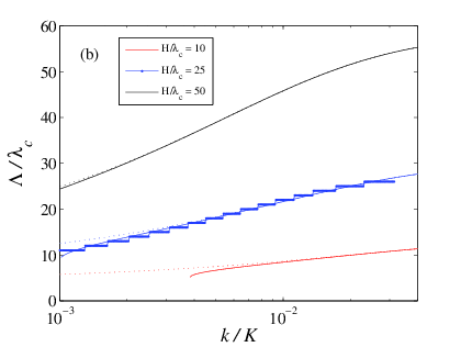
|
Figure J3: Dependence of the
characteristic length Λ on model parameters. Symbols are for
numerics, solid lines for analytics (see
SI), dotted lines for
approximate analytics, Eq.(J33).
(a) Λ vs H/λc for different values of
the interface stiffness k/K = 0.03 (diamonds, red), 0.01
(squares, blue) and 0.003 (circles, black).
(b) Λ vs k/K for fixed H/λc= 10
(bottom, red), 25 (middle, blue, dots), 50 (top, black).
ν = 0.3, L/λc= 100. |
The analytical results together with
the numerical ones are presented in
Fig.J3. Λ is found to increase quasi-linearly with the height of the slider
(Fig.J3a) and to increase quasi-logarithmically with the stiffness of the
interface (Fig.J3b). Comparison with the numerical results shows a quantitative
agreement. We also checked that molecular dynamics simulations of the model
agree with the analytical results.
Discussion. We have studied the onset of sliding
due to propagation of the self-healing precursor cracks. The characteristic length Λ
of the first precursor is controlled by two parameters, H/λc
and k/K, determined by the slider and interface properties.
Importantly, Λ does not depend on the threshold value σs.
This results from the fact that we use linear elasticity and immediate repinning of λ-contacts in a completely relaxed state. As a consequence,
all curves Fig.J2c are unmodified if σs is changed, and
thus the length Λ is also unchanged.
If an additional uniform shear
stress σ0 is applied to the top surface of the slider, then the
thresholds should decrease, σs→ σs− σ0. In such conditions, the crack
will nucleate at a lower macroscopic force and will propagate over a longer
distance. Moreover, if σ0 > σf , where σf
is the Griffith threshold, then the crack will never stop, so that Λ →
∞.
We have considered a constant value of σs along the
interface. If the normal load is non-uniform, e.g., σn(x)
= σn0+ εx as in
top-driven systems with friction-induced torque, then the thresholds will also depend on x, σs(x)
= σs0+ μsεx,
and Λ will depend on the asymmetry parameter ε roughly as Λ(ε)
≈ Λ(0)(1−ε).
We have assumed that broken contacts are immediately restored with zero
stretching. Instead, one may assume that the contacts repin after some delay
time τd. Assuming a constant τd, the width of the
self-healing crack will increase from λc to λc+ vτd,
with v the (minimal) propagation velocity of the crack, and the length Λ will
also increase to Λ + vτd.
In the presence of inertia, which has been neglected in the present quasi-static
model, the TB blocks will be able to continue increasing the load on their
right-hand neighbours even after repinning of their individual λ-contacts. This extra loading is expected to help
breaking further contacts and thus increase the precursor length. In contrast,
the crack nucleation will be unaffected because it originates from a previously
prepared
static state of the system.
We have assumed that all λ-contacts behave as
classical springs with a sawtooth-shape dependence u(σ).
In real systems, they are composed of Nc
micro-junctions with a distribution of thresholds Pc(fs).
If Pc(fs) is wide enough, the
elastic instability will disappear, and the λ-contacts will smoothly slide
with the pushing velocity vd after reaching the stretching
~us, and no discrete precursor will thus be observed.
Here we have considered the first precursor only. The system is left in the
stress state shown in solid line in Fig.J2b. If the system is further loaded, the
left-most λ-contact will again be the first to reach its breaking
threshold, and a second precursor will nucleate. It will propagate through the
stress field left by the previous event, itself modified by the additional
loading, and this scenario will repeat itself. We have run numerical simulations
for the series of precursors and found that all precursors propagate roughly
over the same length Λ. This is not in
agreement with experiments as well as with previous models based on
phenomenological Amontons-Coulomb law, in which successive precursors propagate over increasing lengths.
This discrepancy is resolved, as we checked numerically, if aging of the λ-contacts − newborn contacts have
to be characterized by lower breaking thresholds σs which
then grow with time, e.g., see
 or
or
 − is taken into account. The previously broken region of the interface is characterized by "younger"
contacts and therefore by smaller thresholds, than the "old" unbroken part of the
system. Hence, the next crack will pass this region more easily and propagate
deeper into the system. This process repeats itself until a precursor would span
the whole interface and trigger macroscopic sliding of the interface. Note that
in the case of aging, it appears a competition between the aging, loading and
crack propagation
time scales.
− is taken into account. The previously broken region of the interface is characterized by "younger"
contacts and therefore by smaller thresholds, than the "old" unbroken part of the
system. Hence, the next crack will pass this region more easily and propagate
deeper into the system. This process repeats itself until a precursor would span
the whole interface and trigger macroscopic sliding of the interface. Note that
in the case of aging, it appears a competition between the aging, loading and
crack propagation
time scales.
Finally, we considered the 1D model of the slider. In this case the stress falls
off according to the exponential law, therefore the propagation length (J33)
depends logarithmically on the model parameters. In a 3D model instead the
stress decays according to a power law; this will modify the expression (J33).
Unfortunately, we have no analytics for the 3D model.
Last updated on May 5, 2014 by O.Braun. Copyright ©
by O.Braun. Translated from
LATEX by
TTH