Here we consider the velocity
dependence of kinetic friction with a model which makes minimal assumptions on
the actual mechanism of friction so that it can be applied at many scales
provided the system involves multi-contact interface (MCI). Using the master equation
approach, we investigate the influence of two concurrent processes. First, at a
nonzero temperature thermal fluctuations allow an activated breaking of contacts
which are still below the threshold. As a result, the friction force
monotonically increases with velocity. Second, the aging of contacts leads to a
decrease of the friction force with velocity. Aging effects include two aspects:
the delay in contact formation and aging of a contact itself, i.e., the change
of its characteristics with the duration of stationary contact. All these
processes are considered simultaneously with the master equation approach,
giving a complete dependence of the kinetic friction force on the driving
velocity and system temperature, provided the interface parameters are known.
Almost three centuries ago Charles Coulomb discovered that kinetic
friction does not depend on the sliding velocity. Later, more careful
experiments showed that this law is only approximately valid. Friction does
depend on the sliding velocity, but this dependence is far from universal: some
measurements find an increase when velocity increases, while others find a decay
or even a more complex non-monotonous behavior. A logarithmic dependence, often
quoted, is often only approximate and
observed in a fairly narrow velocity range. What makes the understanding of this
dependence
difficult, is that several phenomena contribute − the thermal depining of
contacts, their aging, and the delay in contact formation.
Here we consider the respective
role of these three contributions to the velocity dependence of friction and
provide analytical treatments in some limits.
Above we described the master equation (ME) approach to describe the breaking
and attachment events. This method allows us to calculate the velocity dependence of friction,
which results from the interplay of two concurrent processes. First, at a
nonzero temperature thermal fluctuations allow an activated breaking of contacts
which are still below their mechanical breaking threshold. This phenomenon leads
to a monotonic increase of the friction force F with the velocity v.
Second, the aging of contacts leads to a decrease of the friction force with
velocity. It includes two processes: the delay in contact formation, i.e., time
lag between contact breaking and remaking, and the aging of a contact itself,
i.e., the change of its characteristics with the time of stationary contact. To
incorporate the latter effect, the master equation must be completed by an
equation for the evolution of static thresholds. Above we considered
thermal and
aging effects
separately; to relate the results to experiments,
however, both contributions must be taken into account simultaneously.
We use the master equation for the
distribution Q(x;X):
| |
[ |
∂
∂x |
+ |
∂
∂X |
+ P(x) |
] |
Q(x;X) =
R(x) Γ(X)
, |
|
(K1) |
where P(x)ΔX describes the
fraction of contacts that break when the slider position changes from X
to X+ΔX. At zero temperature P(x)
is coupled with the threshold distribution Pc(x)
by the relationship
| P(x) = Pc
(x) / Jc (x) , Jc
(x) = |
⌠
⌡ |
∞
x |
dξ Pc(ξ)
. |
|
(K2) |
The function Γ(X) in Eq.(K1) describes the
contacts that form again after breaking,
| Γ(X)
= |
⌠
⌡ |
∞
-∞ |
dξ P(ξ)
Q(ξ; X) |
|
(K3) |
(the delay time is neglected at this stage), and R(x) is the
(normalized) distribution of stretchings for newborn contacts. Then, the
friction force is given by
| F(X) = Nck |
⌠
⌡ |
∞
-∞ |
dx x Q(x; X)
. |
|
(K4) |
The evolution of the system in the quasi-static limit shows that, in the long term, the initial distribution approaches
the
stationary distribution Qs(x) and the total
force F becomes independent of X. Here we concentrate on the steady state (smooth sliding
with a constant velocity v). In what
follows we use R(x) = δ(x) for simplicity. The
steady-state
solution of Eq.(K1) is
| Q (x) =
Θ(x) EP
(x)/C[P] , |
|
(K5) |
where Θ(x) is the Heaviside step function (Θ(x)=1
for x≥0 and 0 otherwise), EP(x)
= exp[−U(x)], U(x) = ∫0x dξ P(ξ),
and C[P] = ∫0∞dx EP(x). Note also that, in the steady
state,
because ∫0∞dξ P(ξ) EP(ξ) =
∫0∞
dU e–U = 1.
The distribution Pc(f)
can be estimated for the
contact of rough surfaces as well as for the contact of polycrystal substrates:
its general shape may be approximated by the function
| Pc(f)
∝ f n exp(−f / f*)
, |
|
(K7) |
where n ≥ 0 depends on the nature of the
interface, or
| Pc(x)
∝ x1+2n exp(−x2/x*2)
, |
|
(K8) |
where x* may be estimated from experiments as Nckx*
≈ Fs. In the SFA/B (surface
force apparatus/balance) experiments, where the sliding surfaces are made of
mica, the interface may be atomically flat over a macroscopic area. But even in
this case the lubricant film cannot be ideally homogeneous throughout the whole
contact area − it should be split into domains, e.g., with different
orientation, because this will lower the system free energy due to the increase
of entropy. Domains of different orientations have different values for the
thresholds fsi , i.e., they play the same role as
asperities in the contact of rough surfaces.
For the normalized distribution of static thresholds given by Eq.(K8) with n=1,
| Pc(x)
= (2/x*) u3e–u2, where
u = x/x*
, |
|
(K9) |
we can express the steady-state solution of the master equation analytically. In
this case
so that at zero temperature we have
| P(x) = (2/x*)
u3/(1+u2) , |
|
(K11) |
| EP(x)
= Jc(x) = (1+u2)
e–u2, |
|
(K13) |
| C[P] = x*/C0 , where
C0 = (4/3√π) ≈
0.752 , |
|
(K14) |
| Q(x) = (C0/x*) (1+u2)
e–u2, u ≥ 0 |
|
(K15) |
and the kinetic friction is
| fk
= Fk /(Nck) = fk0
= C0x*
. |
|
(K16) |
The ME formalism described above can be extended to take into account various
generalizations of the EQ model, such as temperature effects and contact aging,
which are examined in the following sections.
Temperature effects enter in the ME formalism through their effect on the
fraction of contacts that break per unit displacement of the sliding block, P(x),
because thermal fluctuations allow an activated breaking of any contact which is
still below the threshold. For a sliding at velocity v so that X = vt,
the thermally activated jumps can be incorporated in the master equation, if we
use, instead of the zero-temperature breaking fraction density P(x),
an expression PT (x) defined by
where the temperature contribution is given by
| H(x) = |
ω
v |
ekx2/2kBT |
⌠
⌡ |
∞
x |
dξ Pc(ξ) e–kξ2/2kBT |
|
(K18) |
for "soft" contacts or by
| H(x) = |
ω
v |
|
⌠
⌡ |
∞
x |
dξ Pc(ξ) |
[ |
1− |
x
ξ |
] |
1/2
|
e–
kξ2 ( 1–
x/ξ)3/2/2kBT |
|
(K19) |
in the case of "stiff" contacts which have a deep pinning potential so that
their breaking only occurs with a significant probability when their stretching
is close to the threshold. Here ω is the attempt
frequency of contact breaking, ω ~ 1010 s–1.
For concreteness, in what follows we assume that the contacts are soft, Eq.(K18),
and we select n=1 in Eq.(K8), so that Pc(x)
is given by Eq.(K9).
At a nonzero temperature the total rate of contact breaking, Eq.(K17), is equal
to PT(x) = P(x) + (ω/v)
h(x), where
| h(x) = |
1+ (1+b) u2
(1+b)2 |
e–u2 |
|
(K20) |
with
The condition b = 1 defines a crossover temperature
Then, a straightforward integration gives the function UT(x)
= ∫0xdξ PT
(ξ) = U(x) + ΔU(x),
where
| ΔU(x)
= S0(v,T) [erf
(u) − S1(T) u e–u2] |
|
(K23) |
with
| S0(v,T)
= |
ωx*
C0v |
|
(1 + b/3)
(1 + b)2 |
|
|
(K24) |
and
| S1(T)
= |
C0
2 |
|
(1 + b)
(1 + b/3) |
. |
|
(K25) |
The coefficient S1(T) weakly changes with temperature
from S1(0) = 2/√π ≈ 1.128 to S1(∞)
= C0/2 ≈ 0.376. On the other hand,
the coefficient S0(v,T) determines whether the
effect of temperature is essential or not. The temperature-induced breaking of
contacts is essential at low driving velocities only, when S0(v,T)
>> 1. Thus, the equation S0(v*,T) =
1 defines the crossover velocity:
| v*(T)
= |
ωx*
C0 |
|
[1 + b(T)/3]
[1 + b(T)]2 |
. |
|
(K26) |
We see that v* monotonically increases with temperature as
v*(T) ≈ 0.443ωx*T/T* at T << T* and approaches
the maximal value v*≈ 1.33ωx*
at T >> T*.
Then, EPT(x) = e–UT
(x) = (1+u2) e–u2e–ΔU(x),
and we can find the kinetic friction force:
| fk(v,T)
= |
⌠
⌡ |
∞
x |
dx x EPT
(x) |
/ |
|
⌠
⌡ |
∞
x |
dx EPT
(x) . |
|
(K27) |
At a low driving velocity, v << v*, we may put ΔU(x) ≈ S2u,
where
and Eq.(K27) leads to
| fk
≈ x*/S2
= (v/ω) (1 + b)2
. |
|
(K29) |
A linear dependence of the kinetic friction on the driving velocity at low
velocities corresponds to the creep motion due to temperature activated breaking
of contacts and was predicted in several earlier studies, although our approach
allowed us to derive it rigorously. The dependence (K29) may be interpreted as
an effective "viscosity" of the confined interface:
| η
= |
fk
v |
= |
1
ω |
|
[ |
1 + |
kx*2
2kBT |
] |
2
|
. |
|
(K30) |
At a high velocity, v >> v*, when e–ΔU(x) ≈ 1 − S2u
+ 1/2(S2u)2, we
obtain C ≈ 3√π/4
− S2 + (5√π/16)
S22 so that
| fk
≈ fk0 ( 1 − C1S2 + C2S22
) , |
|
(K31) |
where C1 = 5√π/8 − C0
≈ 0.356 and C2 = 16/9π − 1/3
≈ 0.233. Equation (K31) agrees qualitatively with
that found by Persson in the case of b >> 1.
|
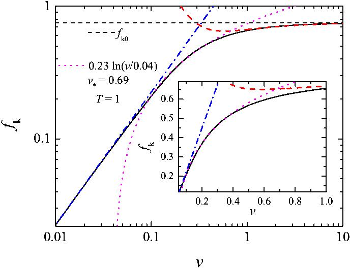 |
Figure K1: The friction force
fk as a function of the driving velocity.
Dash-dotted blue line shows the low-v approximation (K29), dashed
red line shows the high-v approximation (K31), and dotted magenta
line shows a logarithmic fitting. k = 1, ω = 1,
x*= 1, kBT = 1.
|
Approximate expressions (K29, K31)
together with the numerical integration of Eq.(K27) are presented in Fig.K1.
Also we showed a logarithmic fitting which operates in a narrow interval of
velocities near the crossover velocity only. Persson showed that the logarithmic
dependence may be obtained analytically, only if the Pc(x)
distribution has a sharp cutoff at some x = xs as,
e.g., in simplified versions of the EQ model with Pc(x) = δ(x−xs).
|
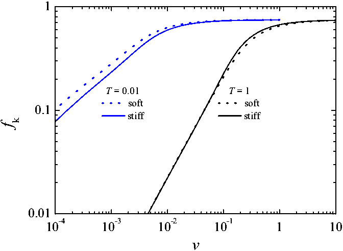 |
Figure K2: The friction force
fk as a function of the driving velocity v
for soft (dotted) and stiff (solid curves) contacts at low temperature
kBT = 0.01 (blue) and high temperature
kBT = 1 (black). k = 1,
ω = 1, x*= 1.
|
Although we cannot obtain analytical
results for the stiff contacts, we calculated the fk(v)
dependences numerically (see Fig.K2), which shows that the effect remains
qualitatively the same.
The aging of contacts was considered
above where, however, we ignored the
temperature-induced breaking of contacts. When aging is taken into account, the
master equation for Q(x,X) must be completed by an equation
for the evolution of Pc(x), which in turns
affects P(x). Let the newborn contacts be characterized by a
distribution Pci(x), while at t
→
∞, due to aging the
distribution Pc(x) approaches a final
distribution Pcf (x). If we assume that the
evolution of Pc(x) corresponds to a stochastic
process, then it should be described by a Smoluchowsky equation
| |
∂Pc
∂t |
= D |
L
|
Pc , where
|
L
|
=
|
∂
∂x |
|
[ |
B(x) + |
∂
∂x |
] |
, |
|
(K32) |
the "diffusion" parameter D describes the rate of aging, B(x) = dU(x)/dx,
and the "potential" U(x)
determines the final distribution, Pcf (x)
∝ exp[ −U(x)
], so that we can write
| B(x) =
−[dPcf (x)
/dx] /Pcf (x) . |
|
(K33) |
However, because the contacts continuously break and form again when the
substrate moves, this introduces two extra contributions in the equation
determining ∂Pc/∂X
in addition to the pure aging effect described by Eq.(K32): a term P(x;X) Q(x;X)
takes into account the contacts that break, while their reappearance with the
threshold distribution Pci(x) gives rise to the
second extra term in the equation. Thus, the evolution of Pc
is described by the equation
| ∂Pc(x;X)/∂X −
DvLPc(x;X) +
P(x;X) Q(x;X)
= Pci(x) Γ(X) , |
|
(K34) |
where Dv≡ D/v, and v = dX(t)/dt
is the driving velocity. Finally, we come to the set of equations (K1−K3, K34).
For the steady-state regime, Eq.(K34) reduces to
| Dv
C[P] |
L
|
Pc(x)
= P(x)EP(x)
− Pci(x) , |
|
(K35) |
where we used Eqs.(K5) and (K6). Taking also into account the
identity P(x)EP(x) = Pc(x), we finally come to the
equation
| Dv
C[P] |
L
|
Pc(x)
= Pc(x) −
Pci(x) . |
|
(K36) |
It was shown above that the kinetic friction monotonically decreases with the
driving velocity as Fk(v) −
Fk(0) ∝ −v/D in the low-velocity limit and Fk(v) − Fk(∞)
∝ D/v in the high-velocity case. One
may expect that at low velocities this decreasing will compensate the friction
increasing due to temperature induced jumps. The problem, however, is more
involved.
When the temperature effects are incorporated, Eq.(K36) for the function Pc(x)
in the steady state takes the form
| Dv
C[PT] |
L
|
Pc(x)
= Pc(x) −
Pci(x) . |
|
(K37) |
|
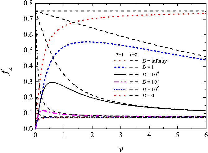 |
Figure K3: The kinetic
friction force fk as a function of the driving
velocity v for different values of the aging rate: D =
∞ (red dotted), 1 (blue short-dashed), 10–1
(black solid), 10–2 (magenta
dash-dotted), 10–3 (blue
short-dotted), and D = 0 (red dotted curve). k = 1,
ω = 1, kBT = 1;
the initial and final Pc(x)
distributions are given by Eq.(K9)
with x*i = 0.1 and x*f
= 1 correspondingly. Dashed curves shows the dependences at T = 0.
|
|
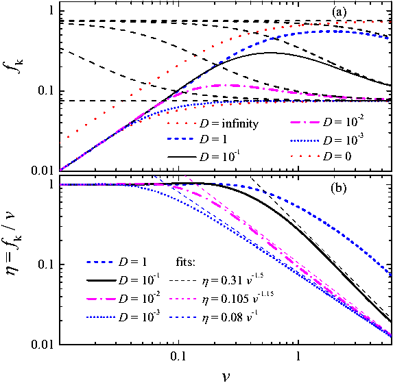 |
Figure K4: Same as in Fig.K3
in log-log scale. (b) The dependences of the effective "viscosity"
η = fk/v on the
velocity v (dashed lines show power-law fits). .
|
Numerical solutions of Eq.(K37) are presented in Figs.K3 and K4a: the initial
increase of the kinetic friction F with the driving velocity v due
to the temperature activated breaking of contacts is followed by the decrease of
F due to contacts aging. Figure K4b shows also the dependence of the
effective "viscosity" η = fk
/v on the driving velocity v. It is constant at low velocity and
then decreases; the latter may be approximately fitted by a power law
η(v) ∝ v–α
with the exponent α changing from 1.5 to 1 as D
decreases.
Using the definition (K32) of the operator L and Eq.(K33) for the
function B(x), the l.h.s. of Eq.(K37) may be rewritten as
| DvC |
L
|
Pc(x)
= DvC |
d
dx |
|
[ |
Pcf
(x) |
d
dx |
|
Pc(x)
Pcf (x) |
] |
, |
|
(K38) |
while the r.h.s. of Eq.(K37) may be presented as
| Pc(x)
− Pci(x)
= − |
d
dx |
[ Jc(x) − Jci
] , |
|
(K39) |
where Jci(x) = ∫x∞dξ Pci(ξ).
Using Eqs.(K38) and (K39), we can find the first integral of Eq.(K37):
| Dv
C[PT] Pcf (x) |
d
dx |
|
[ |
Pc(x)
Pcf (x) |
] |
= Jci(x) − Jc(x)
. |
|
(K40) |
Integration of Eq.(K40) leads to an integral equation for the function Pc(x):
| Pc(x)
= Pcf (x) |
[ |
1 + |
v
DC[PT] |
|
⌠
⌡ |
x
0 |
|
Jci(ξ) − Jc(ξ)
Pcf (ξ) |
dξ |
] |
. |
|
(K41) |
Substituting Jc(x) ≈
Jcf (x) = ∫x∞
dξ Pcf (ξ)
into the r.h.s. of Eq.(K41), one may analytically find the low-velocity behavior
of the kinetic friction, for example, the decrease of fk
with v for T=0. At a nonzero temperature, however, aging does not
affect the low-velocity behavior (K29) and only reduces the interval of
velocities where Eq.(K29) is valid, as demonstrated in Figs.K3 and K4. Indeed,
at v → 0 and T > 0 the main
contribution to PT(x) comes from the function
H(x) ∝ ω/v
in Eq.(K17), which only weakly depends on Pc(x).
|
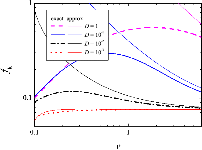 |
Figure K5: The kinetic
friction force fk as a function of the driving
velocity v for different values of the aging rate D = 1
(magenta dashed), 10–1 (blue
solid), 10–2 (black dash-dotted)
and 10–3 (red dotted curve) as
compared with approximate expressions (thin solid curves). k = 1,
ω = 1, kBT = 1;
the initial and final Pc(x)
distributions are given by Eq.(K9) with x*i= 0.1
and x*f = 1 correspondingly.
|
The limit Dv≡ D/v → 0 may be studied with the help of Eq.(K37) by substituting Pc(x) ≈ Pci(x)
into its left-hand side. For the function (K9), this approach gives
| Pc(x)
− Pci(x) ≈ − |
16 DvC[P]
x*i xif2 |
ui
e–ui2
|
[ |
1 −
|
1
2 |
ui2
|
] |
|
|
(K42) |
and
| Jc(x)
− Jci(x) ≈ |
4 DvC[P]
xif2 |
ui4
e–ui2, |
|
(K43) |
where ui= x/x*i and
| |
1
xif2 |
= |
1
x*i2 |
−
|
1
x*f2 |
. |
|
(K44) |
Then, taking the corresponding integrals, we obtain to first order in v–1
| C ≈ x*i ( C0–1
− S2 + C12S3 ) |
|
(K45) |
and
| fk
≈ |
x*i2
C |
[ 1 − (C0
+ C1) S2 +
C12 S3 ] , |
|
(K46) |
where
C12 ≈ 1.324 and C12
≈ 1.789 are numerical constants. A comparison of the
exact and approximate expressions is shown in Fig.K5.
Finally, let us take into account the
delay in contact formation following the work of Schallamach. Let τ be the delay time, N be the total number of
contacts, Nc be the number of coupled (pinned)
contacts, and Nf = N−Nc
be the number of detached (sliding) contacts. The fraction of contacts that
detach per unit displacement of the sliding block is Γ(v,T)
= ∫dx P(x) Q(x),
i.e., when the slider shifts by ΔX, the number
of detached contacts changes by NcΓ ΔX,
so that Nf = ΓvτNc.
Using Nc+Nf = N, we
obtain Nc = N / (1 + Γvτ) and Nf = N
Γvτ/ (1 +
Γvτ). If we define x = 1/Γ and
vd = x/τ,
we can write
| Nc =
|
N
1 + v/vd |
and Nf
= |
Nv/vd
1 + v/vd |
. |
|
(K48) |
|
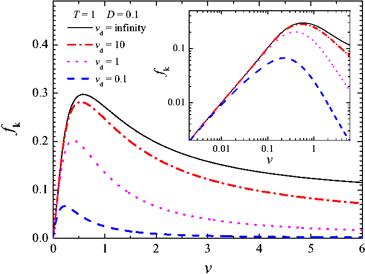 |
Figure K6: The kinetic
friction force fk as a function of the driving
velocity v for different values of the delay time: vd
=
∞ (black solid), 10 (red dot-dashed), 1
(magenta dotted) and 0.1 (blue dashed curve) for D = 0.1 and kBT = 1 (other parameters as in Fig.K3). Inset shows the same in
log-log scale.
|
The coupled contacts produce the force fk defined
above by the steady-state solution of the master equation. The combined
dependence which incorporates temperature effects, aging and delay in contact
formation, is shown in Fig.K6
for different values of the parameter vd.
However, above we assumed that the sliding contacts experience zero friction,
while these contacts may experience a viscous friction force fl
= ηlv, where
ηl corresponds to the (bulk)
viscosity of the liquid lubricant. In this case the kinetic friction should be
additionally multiplied by a factor β(v) = 1 +
v2/vhvd ,
where vh= fk
/ηl (vh>> vd). Such a correction may be expected at huge
velocities only, e.g., for v ~ 1 m/s. In this
case the function Fk(v), after decreasing,
reaches a minimum at a velocity v0 ≈
(vhvd)1/2,
and then increases according to a law fk(v)
∝ηlv.
Note that the viscous friction which comes from the excitation of phonons in the
substrates, as shown in MD simulation, may also depend on the velocity, e.g., as
ηl ∝
v4.
For a real system, the results presented in the previous sections allow the
calculation of the kinetic friction force Fk(v,T)
provided the parameters of the model are known. In this section section we
examine how they can be evaluated from experiments.
The contact parameters k and ω may be
estimated with the help of elastic theory. Let us assume that a contact has a
cylinder shape of height h (the thickness of the interface) and radius
rc, so that it is characterized by the section Ai= πrc2,
the (geometrical) inertial momentum I = πrc4/4, a mass density ρ and a Young modulus E. If
the cylinder foot is fixed and a force Δf is
applied to its top, the latter will be shifted on the distance
Δx = Δf h3/3EI (the problem of bending pivot, see Sec.20, example 3 in [LL]). Thus,
the effective elastic constant of the contact is k = Δf/Δx = 3EI/h3.
The minimal frequency of bending vibration of the pivot with one fixed end and
one free end, is given by ω ≈
(3.52/h2) (EI/ρAi)1/2
(see Sec.25, example 6 in [LL]).
Next, let a be the average distance between the contacts, so that the
total area of the interface is A = Na2, and introduce the
dimensionless parameter γc= rc/a (γc < 0.5). The threshold
distance x* may be estimated as follows. At the beginning,
when all contacts are in the unstressed state, the maximal force the slider may
sustain is equal to F* ≈ Nkx*
(this force corresponds to the first large stick spike in the F(t)
dependence at the beginning of stick-slip motion at low driving). Thus, we
obtain that kx* ≈ a2σ*, where σ*= F*/A is the maximal shear stress.
Let us consider a contact of two rough surfaces and assume that a = h = rc.
Then we obtain
for the attempt frequency,
for the contact elasticity, and
for the threshold distance. For steel substrates we may take ρ = 104 kg/m3 for the mass density, E = 2×10¹¹ N/m2
for the Young modulus, and σc = 109 N/m2
for the plasticity threshold. Assuming that σ*= σc and rc
≈ 1 μm, we find that ω ≈ 7.9×10⁹ s–1,
k ≈ 4.7×10⁵ N/m, x*
≈ 2.1×10⁻⁹ m,
b ≈ 2.7×10⁸ for room temperature
(i.e., b >> 1), so that the crossover velocity is quite low, v*≈ 0.03 μm/s.
Now let us consider a lubricated system, e.g., the one with a few OMCTS layers
as studied by Klein [J. Klein, Phys.Rev.Lett. 98, 056101 (2007)]
and Bureau [L. Bureau, Phys.Rev.Lett. 104, 218302 (2010)],
and assume that the lubricant consists of solidified islands which melt under
stress as proposed by Persson.
In this case, instead of using the Young modulus, let us assume that x*= rc; this allows us to find the parameter EI =
ah3σ*/3γc.
Then, the elastic constant is k = aσ*/γc, the attempt frequency is
the parameter b is given by
and in the case of b >> 1 the crossover velocity is
| v*
≈ γcωa /3C0b
≈ kBT
/ |
√ |
a5hρs*γc3
|
. |
|
(K54) |
For a four-layer OMCTS film one may take ρ = 956 kg/m3,
h ≈ 3.5×10⁻⁹ m,
F*≈ 2×10⁻⁵ N
and A ≈ 10–10 m2
so that σ*≈ 2×10⁵ Pa. Assuming γc=
0.5 and a ≈ 1 μm,
we obtain for room temperature, kBT = 4×10–21 J,
that ω ≈ 8×10⁸ s-1
and b ≈ 1.25×10⁷, i.e. this system
is in the low-temperature limit too, although the crossover velocity is much
higher than for rough surfaces, v* ≈
16 μm/s.
|
 |
Figure K7: The shear stress
σ as a function of the shear rate dγ/dt for different values of the OMCTS film thickness from nl=2
to 6 monolayers.
Inset: the crossover velocity v* as a
function of the number of layers.
|
Moreover, we may calculate the dependence fk(v)
for different thicknesses of the lubricant film. If the film consists of nl
layers, then the film thickness is h = nld,
where d ≈ 8.75 Ĺ is the diameter of the OMCTS
molecule. Let us assume that the maximal shear stress exponentially decreases
with the number of layers according to the results of MD simulation, σ*= σ0
e–βnl ,
where β ~ 1 is a numerical constant. Taking
σ0= 4×10⁶ N/m2 and
β = 1.5, we obtain the dependences of the shear
stress σ = Fk/A on
the shear rate dγ/dt = v/h shown in
Fig.K7, which may be compared with the experimental dependences (Fig.2a) of
Bureau.
Note that our approach may overestimate the value of the crossover velocity v*.
First, the crossover will occur earlier if the delay and/or aging effects play a
significant role. Besides, at low temperatures the stiff contacts lead to higher
"viscosity" and lower values of v* than the soft contacts
considered above (see Fig.K2). Second, we completely ignored the elastic
interaction between the contacts. If the latter would be incorporated, a
breaking of one contact may stimulate neighboring contacts to break as well,
i.e., the value of the parameter a should describe such a cooperative
"contact" size which may be much larger than those of individual ones
(see
 ).
).
Giving a quantitative evaluation of the influence of aging on the velocity
dependence of the friction coefficient is harder than for the temperature
dependence due to insufficient experimental data. Aging appears to cause a
decrease of friction as velocity increases, and thus, when such a behavior is
observed experimentally, it can be considered as a strong indication of the
presence of aging. Our analysis indicates that the combined effect of
temperature and aging leads to a maximum in the friction coefficient versus
velocity. Therefore, when aging is manifested by a decreasing friction versus
velocity, extending the experiments to lower velocities and temperatures might
detect the maximum and thus provide some quantitative data to evaluate the aging
parameters.
Although the aim of our work was to find the dependence of the kinetic friction
on the driving velocity, our approach allows us to find the dependence on
temperature as well. However, the behavior of a real tribological system is more
involved, because all parameters may depend on temperature T in a general
case. For example, the delay time τ may exponentially
depend on T if the formation of a new contact is an activated process;
the same may be true for the aging rate D. In this case one may obtain a
nonmonotonic temperature dependence of friction with, e.g., a peak at cryogenic
temperatures.
Thus, in a general case, the friction
linearly increases with the velocity (this creep motion may be interpreted as an
effective "viscosity" of the confined film), passes through a maximum and then
decreases due to delay/aging effects. The decay may be followed by a new growth
in friction in the case of liquid lubricant. Estimation showed that for the
contact of rough surfaces, the initial growth of friction should occur at quite
low velocities, v << 0.1 μm/s, so that for
typical velocities the friction is independent on velocity in agreement with the
Coulomb law. However, for the case of lubricated friction with a thin lubricant
film which solidifies due to compression, the fk(v)
dependence is essential, and the linear dependence may stay valid up to
velocities v ~ 10 −103 μm/s.
At higher velocities the growth saturates and the fk(v)
dependence may be fitted by a logarithmic law. The latter velocity interval is
narrow if the distribution of static thresholds is wide; the logarithmic law may
operate for a wide interval of velocities when the thresholds are
approximately identical, e.g., for the singular distribution Pc(x) = δ(x-xs).
We emphasize that our ME approach is only valid for a system with many contacts,
for example, N > 20 at least. When the contact is due to a single atom as
it may occur in the AFM/FFM devices, the friction can be accurately described by
the Prandtl-Tomlinson model and should follow the logarithmic fk(v)
dependence, fk (v) ∝
( lnv/v0 )2/3. But if the AFM/FFM tip is not
too sharp so that the contact is due to more than one atom, the logarithmic
dependence is only approximate.
In this work we had in mind that contacts correspond to real asperities in the
case of the contact of rough surfaces or to "solid islands" for the lubricated
interface. However, the ME approach also operates when the contact is due to
long molecules which are attached by their ends to both substrates. Such a
system was first studied by Schallamach and then further investigated by several
authors. Note that when all molecules are identical, they are characterized by
the same static threshold, i.e., this system is close to the singular one, where
the logarithmic fk(v) dependence has to have a
wide interval of operation.
Finally, let us discuss restrictions of our approach. First of all, we assumed
the somehow idealized case of wearless friction; wearing may mask the predicted
dependences. Besides, the interface is heated during sliding; this effect is
hard to describe analytically as well as to control experimentally. Then, we did
not estimated the delay/aging parameters; moreover, these parameters, e.g., the
delay time τ, may depend on the driving velocity v.
Besides, we assumed the simplest mechanism of aging described by the
Smoluchowsky equation, while the real situation may be more involved, e.g., it
may correspond to the Lifshitz-Slözov mechanism. Also, we assumed that the
reformed contacts appear in the unstressed state, R(x) = δ(x)
in Eq.(K1), which may not be the case in real systems.
The most important issue, however, is the incorporation of the elastic
interaction between the contacts as well as elastic deformation of substrates at
sliding (see
 ).
).
Published in: O.M. Braun and M. Peyrard, Phys. Rev. E 83 (2011) 046129
"Dependence of kinetic friction on velocity: Master equation approach"
Last updated on April 22, 2014 by O.Braun. Copyright ©
by O.Braun. Translated from
LATEX by
TTH
![]() ).
).
![]() ).
).