Above we used a simpler model, where the slider was treated as a rigid body. Due to the non-rigidity of the substrates, however, several length scales naturally appear in the problem. First, different regions of the interface may exhibit independent displacements if these regions are separated by distances r >> λLO (the Larkin-Ovchinnikov length, see A.I. Larkin and Yu.N. Ovchinnikov, J. Low. Temp. Phys. 34 (1979) 409-428); however, for the contact of stiff rough solid surfaces λLO takes unphysically large values ~10100 000m. Second, deformation of the solid substrates leads to the elastic interaction between the contacts. Elasticity will correlate variations of forces on nearest contacts over some length λc known as the elastic correlation length. Third, displacements in one region of the slider will be felt in other regions on the distance scale set by of a screening length λs. Finally, the breaking of one contact may stimulate neighboring contacts to break too (the so-called concerted, or cascade jumps), following which an avalanche-like collective motion of different domains of the interface may appear; such self-healing crack will propagate for some distance Λ.
In what follows we discuss collective effects in the frictional interface trying to clarify, in particular, the following questions: (i) what is the law of interaction between the contacts; (ii) at which scale can the slider be considered as a rigid body, or what is the coherence distance λc within which the motion of contacts is strongly correlated; (iii) whether the interaction effects can be incorporated in the master equation approach; (iv) how does the interaction between the contacts modifies the interface dynamics; (v) what is the screening length λs; (vi) when do avalanche motion of contacts (a self-healing crack) appear, what is the avalanche velocity and (vii) the propagation length Λ?
Before proceeding with the analytical and numerical developments, let us discuss briefly possible values of model parameters for a typical tribological system.
Elastic constant of the slider. The slider (shear) elastic constant K is equal to K = [E/2(1+ν)](LxLy/H), where Lx, Ly and H are the slider dimensions, E and ν are the substrate Young modulus and Poisson ratio, respectively. For example, for a steel slider of Young's modulus E=2×10¹¹ N/m2, Poisson's ratio ν=0.3 and the size Lx×Ly×H = 1 cm × 1 cm × 1 cm, we obtain K ~ 109 N/m.
Rigidity of the interface contacts. Next, let us characterize the typical
magnitudes of the contact stretching length xc and
stiffness kc. Assume the slider and the substrate to be
coupled by N = LxLy/a2
contacts, and that the contacts have a cylindrical shape of (average) radius
rc with a distance a between the contacts. It is
useful to introduce two dimensionless parameter. The first parameter γ2= rc/a
characterizes the density of contacts and may be estimated as follows. Consider a cube of linear size L on a table. The weight of the cube Fl= ρL3g (ρ
is the mass density and g=9.8 m/s2) must be compensated by
forces from the contacts, Fl= Nrc2σc, where σc
is the plastic yield stress. Then, γ22= (Nrc2)/(Na2)
= (ρL3g)/(σcL2), or
γ2= (ρLg/σc )1/2.
Taking L = 1 cm, ρ = 10 g/cm3 and
σc= 109 N/m2
(steel), we obtain γ2≈ 10
The second dimensionless parameter γ1= kc/Ea characterizes the stiffness of the contacts. To estimate γ1, assume that contacts have the shape of a cylinder of radius rc and length h (h is the thickness of the interface). Suppose in addition that one end of a contact ("column") is fixed, and a shear force f is applied to the free end. This force will lead to the displacement x = f /kc of the end, where kc= 3EcI/h3, Ec is the Young modulus of the contact material and I = πrc4/4 is the moment of inertia of the cylinder. In this way we obtain kc= (3π/4)(Ecrc)(rc/h)3, so that γ1= (3π/4)(Eca3/Eh3)(rc/a)4= γ0γ24 with γ0= (3π/4)(Ec/E)(a/h)3. For the contact of rough surfaces, where Ec= E and a > h, we have γ0 > 1, while for lubricated interfaces where Ec<< E, one would expect γ0 < 1.
An estimate of characteristic values leads to rc~ (10
First let us consider the question how
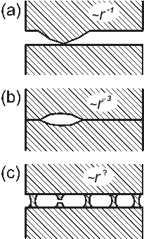
the forces on contacts are redistributed when one of contacts breaks. A qualitative picture of elastic interaction is
presented in Fig.I1 (left). When a contact acts on the surface at r=0 with
a force f, it produces a displacement field u(r) ∝
r
 |
|
Figure I1:
Left: decaying of the displacement field at the interface (schematic): (a) for a single contact u(r) ∝
r (b) for a single hole u(r) ∝
r (c) for the array of contacts.
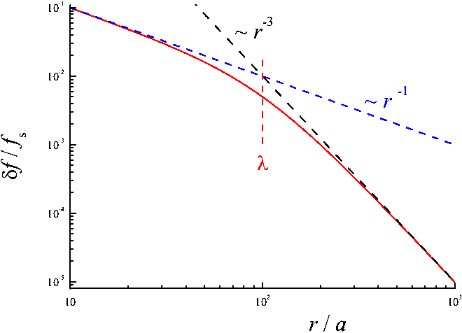
Right: change of forces on contacts when the central contact is removed (γ1= 0.06). |
In what follows we show that the interaction
between the contacts demonstrates a crossover from the r
Analytics. Let us consider an array of N elastic contacts with coordinates ri={xi, yi, 0}, i=1,...,N between the two (top and bottom) substrates. If the interface is in a stressed state, the contacts act on the top substrate with forces fi={fix, fiy, fiz}. These forces produce displacements ui(top) of the (bottom) surface of the top substrate. The 3N-dimensional vectors U(top)={ui(top)} and Ft={fi} are coupled by the linear relationship U(top) = G(top)Ft. The elements of the elastic matrix G(top) (known also as the elastic Green tensor) for a semi-infinite isotropic substrate are given in the Landau and Lifshitz texbook:
|
In the equilibrium state, the forces that act from the contacts on the bottom substrate, must be equal to Fb = −Ft according to third Newton's law. These forces lead to displacements of the (top) surface of the bottom substrate, U(bottom)= −G(bottom)Ft. The elements of the bottom Green tensor G(bottom) are defined by the same expressions (I9) except the xz elements for which Gix, jz(bottom)= −Gix, jz(top) (if the substrates are identical, the z displacements are irrelevant). Thus, the relative displacements at the interface due to elastic interaction between the contacts are determined by
|
(I10) |
On the other hand, the forces and displacements are coupled by the diagonal matrix (the contacts' elastic matrix) K with elements Kiα, jβ= kiαδijδαβ (α,β = x,y,z):
|
(I11) |
Combining Eqs.(I10) and (I11), we obtain F = K ( U0− GF ), or
|
(I12) |
If now one changes the contacts' elastic matrix, K → K + δK, then the interface forces should change as well, F → F + δF. From Eq.(I12) we have δF = (δB)KU0+ B(δK)U0. Then, δB may be found from the equation δ[B(1+KG)] = (δB)(1+KG) + B(δK)G = 0 . Therefore, finally we obtain:
|
(I13) |
Now, if we remove the i*th contact by putting δkiα= −kiαδii* and then calculate the resulting change of forces on other contacts, we can find a response of the interface to the breaking of a single contact as a function of the distance r = ri− ri* from the broken contact.
Numerics. Equation (I13)
may be solved numerically by standard methods of matrix algebra. We explore an
array of identical contacts, kiα= kc and (U0)iα= u0δαx
for all i, organized in a square 89×89 lattice with spacing a=1,
with the broken contact i* at the center of the lattice. For
singular terms of the Green function (9)
we apply a cutoff at rii= rc.
Numerical results depend on two dimensionless
parameters. The first one,
γ1= kc/E*a, determines the stiffness of the array of contacts relative the
substrates (here E*
 |
 |
|
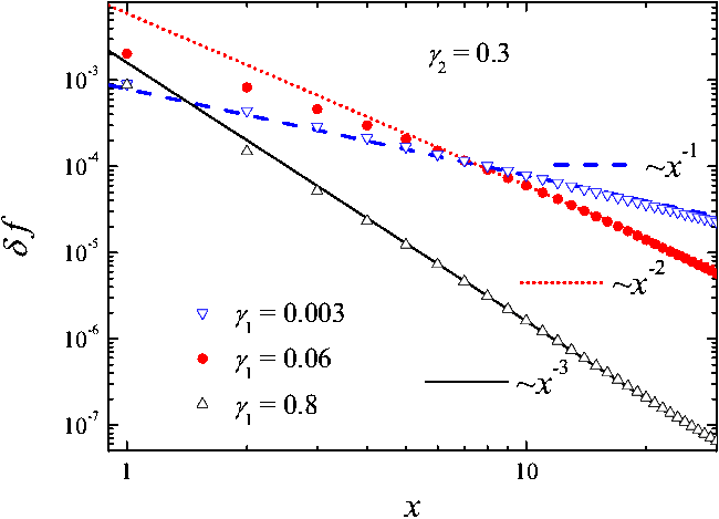
Figure I2: Dependence of the change of forces δf(r) on the distance x from the broken contact. Left: δf(r) for three values of the interface stiffness: γ1= 0.003 (blue down triangles, dashed line), 0.06 (red solid circles, dotted line) and 0.8 (black up triangles, solid line) at fixed value of γ2=0.3 (ν=0.3). The lines show the corresponding power laws. Right: schematic picture. |
|
The numerical results for the x-component of dimensionless force δf = δFx/(kcu0)
are presented in Fig.I2.
The function δf(r) exhibits a crossover from a slow Coulomb-like decay δf(r) ∝ r
|
(I14) |
The rigid slider corresponds to the limit E →
∞, or γ1→ 0. Therefore, the slider may be considered as a
rigid body (e.g., in MD simulation), if its size is smaller than
λc. For example, for a steel slider estimation
gives λc/a
~102. Up to distance λc the contacts strongly interact. If the ith
contact breaks and its stretching changes on |δxi|
≈
xc, then the force on the jth contact at a
distance rij < λc
away, changes by δfj
≈ κkca
δxi/rij , where the
dimensionless parameter κ < 1 characterizes
the strength of interaction (numerics gives κ
~10
Let us now include the dynamical
interaction between the contacts. When a contact breaks, the now unsustained
shear stress must be redistributed among the neighboring contacts. Using the
results of previous section, we assume
that because of elastic interaction between the contacts i and j,
the forces acting on these contacts have to be corrected as fi→ fi− Δfij and fj→ fj + Δfij,
where Δfij = kij(xj− xi)
in linear approximation. For example, let at the beginning the contacts be
relaxed, xj(0) = xi(0) = 0.
Due to sliding motion, all stretchings grow together, so that still Δfij= 0. At some instant
t let the jth contact break, xj(t)
→ 0, while the ith contact is still stretched,
xi(t) > 0. Clearly, as the jth contact
breaks, the force on the ith contact increases, Δfij(t) = −kijxi(t) < 0. The amplitude of interaction decreases with the distance r
from the broken contact as Δf ∝ r
Figures I3 and I4 show the result of simulations for different values of the dimensionless strength of the interaction
|
(I15) |
|
|
Figure I3: The steady state distribution Qs(x) for the rectangular threshold distribution Pc0(x) with xs= 1 and Δxs= 0.25 and different values of the interaction strength κ = 0, 0.02, 0.06, 0.1, and 0.5.
The EQ simulations (dotted) are compared with the ME results (solid blue curves). |
|
|
Figure I4: Onset of sliding: the initial part of the dependence of the friction force F on the slider displacement X for different strength of interaction κ = 0.005 (black), 0.01 (cyan), 0.03 (red), 0.05 (blue), and 0.07 (magenta).
Dotted curves show the results of EQ simulation, and solid curves, the mean-field ME approach.
The threshold distribution Pc0(x) has the rectangular shape with xs= 1 and Δxs= 0.25. |
While the EQ model may be studied numerically only, it would be useful to have some analytical results. In what follows we show that the EQ results may be reproduced within the ME approach by using "effective" Pc(x) and R(x) distributions defined in a mean-field fashion.
Smooth sliding. Using the steady state solution of the ME, one may approximately recover the functions Pc(x) and R(x) if the stationary distribution Qs(x) is known. Indeed, for small x, where P(x) is close to zero, the left-hand side of Qs(x) allows us to find R(x) as R(x) ∝ Qs'(x), while the right-hand side of Qs(x), where x~xc and the contribution of R(x) to the shape of the steady state distribution is negligible, gives us Pc (x) ∝ P(x)Qs(x) ∝ −Qs'(x). (e.g., see Fig.2 in the ME-Introduction). Thus, differentiating the function Qs(x) obtained in the EQ simulation, we may guess shapes of the effective distributions Pc(x) and R(x) which, when substituted in the ME, would produce a solution Qs(x) close to that obtained in the EQ simulation.
Using the simulation results, let us suppose that the detached contacts form again with nonzero stretchings, i.e., that the distribution R(x) is shifted to positive stretching values,
|
(I16) |
|
(I18) |
The results of this procedure for the rectangular distribution Pc0(x) are shown in Fig.I3. We see that with a proper choice of the parameters α, β and γ, the ME solutions Qs(x) perfectly fit the numerical EQ results (for the parameters α, β and γ in Fig.I3 we used expressions β = 1 + b1κ, α = b2κ/β and γ = b3α − b4α2 with the coefficients b1= 18, b2= 9.6, b3= 0.142 and b4= 0.232). Results of similar quality were also obtained for other simulated cases, e.g., for larger radius of the interaction or for wider threshold distribution Pc0(x).
The dependences of the fitting parameters α, β and γ on the dimensionless strength of interaction κ may be found in the following way. Clearly that for noninteracting contacts we have α = γ = 0 and β = 1. It is reasonable to expect that in the lowest approximation α,γ ∝ κ and β−1 ∝ κ. Indeed, the shift of the effective distribution Pc(x) appears because of the interaction, αfc= ΣjΔfij , therefore at small κ we have approximately
|
(I19) |
Thus, the interaction makes the threshold distribution Pc(x) narrower by a factor β and shifts its
center to the left-hand side, xc→ νxc, where
ν = α + β
Onset of sliding. The beginning of motion when started from the relaxed configuration, Q(x; 0) = δ(x), cannot be explained by the approach used above, because the effective distribution Pc(x) is "self-generated" during smooth sliding, when the process of contacts breaking-reattachment is continuously operating. Nevertheless, the initial part of the F(X) dependence may still be described by the effective ME approach, but with the modified "forward" threshold distribution given by the expression
|
(I20) |
Numerics shows that with a proper choice of the fitting parameters β0 and ε0 for a given value of κ, the initial part of the function F(X) may be reproduced with quite high accuracy. Moreover, for a rather wide range of κ values, the EQ simulation results may be reproduced by the ME approach with a reasonable accuracy using only three fitting parameter c1, c2 and κc, if the parameters β0 and ε0 in Eq.(I20) are given by the expressions β0= 1 + c1κ/(1 − κ/κc) and ε0 =c2(β0- 1), where the parameter κc corresponds to the critical interaction strength when many contacts begin to break simultaneously. For κ > κc, the drop of F(X) becomes jump-like, so that K*= ∞ and stick-slip will appear for any stiffness of the slider K < ∞; the value of κc may be estimated from the equation αxc~ Δxs.
For the rectangular shape of the distribution Pc0(x) the result of this procedure is demonstrated in Fig.I4 (the fitting parameters are c1= 33.9, c2= 3.0 and κc= 0.074).
Of course, the Pci(x) function, Eq.(20),
can describe only the initial part of the F(X) dependence, when
F(X) grows, reaches the first maximum and then decreases. To simulate
the whole dependence F(X), one would have to involve the evolution
of Pc(x) with sliding distance, e.g., as some
"aging" process Pci(x) →
Pc(x) (see
![]() ) with the initial
distribution Pc, ini(x)
= Pci(x) and the final one Pc,
fin(x) = Pc(x).
) with the initial
distribution Pc, ini(x)
= Pci(x) and the final one Pc,
fin(x) = Pc(x).
Stick-slip vs smooth sliding. As mentioned above, stick-slip appears as a result of elastic instability which is controlled by the relation between the slider stiffness K and the effective interface stiffness K*. For noninteracting contacts K*≈ Ksxc/Δxs; because typically Δxs~ xc, estimates give K*< K so that stick-slip would never appear. The interaction between contacts strongly enhances the elastic instability thus making stick-slip much more probable. Indeed, because of the effective shrinking of the threshold distribution, the parameter K* increases roughly as K*→ Keff*~ β0K*, i.e., the effective interface stiffness Keff* grows with the strength of interaction κ, and the elastic instability can now emerge. For example, for a realistic threshold distribution the dependence of Keff* on the strength of interaction κ is shown in Fig.I5.
|
|
Figure I5: The effective
interface stiffness Keff*
(normalized on the noninteracting value) as a function of the strength
of interaction κ for the realistic threshold
distribution Pc0(x) = (2/xs)
u3e |
The strength of interaction between
the contacts may be found as κ ≈ κa/xc,
where realistic values of the dimensionless parameter κ
are of the order κ ~ 10
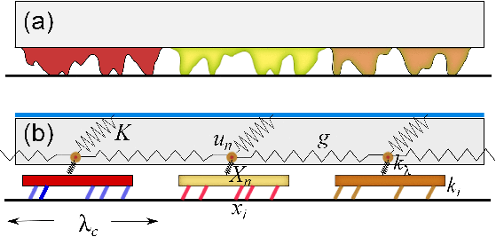
Thus, within the area λc2 the substrate can be considered as rigid. This allows us to split the friction problem in two parts. At the smaller scale one can study the collective behavior of a set of contacts attached to a "rigid body" of size λc, which is itself related to the bulk by an elastic spring of rigidity kλ describing the elastic response of the part of material which is between the asperities and the bulk. We henceforth call λ-contact this set of microscopic contacts. The parameters of the λ-contact, such as its breaking threshold, or the effective elastic constant (the relation between its stretching and the shear stress applied between the bulk and the underlying substrate) may be calculated with the help of the ME approach, incorporating the interaction between the microcontacts within the MF approximation as described above. The strong inter-contact interaction leads to a narrowing of the effective threshold distribution for contact breaking and enhances the chances for an elastic instability to appear.
 |
| Figure I6: Schematic view explaining the decomposition of the friction problem into elements that are studied separately. (a) Contact of a rough interface with a flat substrate. We consider the bulk material (rectangle) and the interfacial rough layer, which has many asperities in contact with the substrate. (b) The reduced model. Asperities are correlated over a length λc and form a "λ-contact" composed of asperities, having elastic constants ki, and a piece of material, between the asperities and the bottom of the bulk volume, having an elasticity kλ. The nth λ-contact is attached to the bulk material at position un. The bulk material is described by an elastic constant g that corresponds to its deformation along the interface, and the elastic constant K which is associated to its shear deformation when its top surface is subjected to some shear stress. |
At a larger (mesoscopic) scale the elastic deformation of the sliding block cannot be ignored. The λ-contacts are elastically coupled through the deformation of the bulk. On distances above the correlation length, r > λc, the interaction between the λ-contacts leads either to screening of local perturbations in the interface, or to appearance of collective modes − frictional cracks propagating as solitary waves. Thus, to develop a full theory of friction on the mesoscale, one has to take into account the elastic deformation of the sliding blocks and the interface by introducing a position dependent distribution Q[x, X(r)], where r = {x,y} denotes the position of the λ-contact on the interface, and X(r,t) describes the local translation of the interface averaged over the λc scale. The solution of the master equation (or a set of equations if the aging is included) then provides a local force (stress) at the interface F(r,t). The master equation has then to be coupled to an equation describing the elastic deformation of the block with the boundary condition at the interface, subjected to the contact forces F(r,t) at each point r. Such a program is realized in next section.
Last updated on May 3, 2014 by O.Braun. Copyright © by O.Braun. Translated from LATEX by TTH