|
Constant-force algorithm: hysteresis |
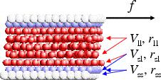 |
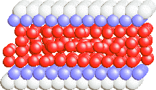
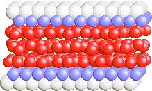
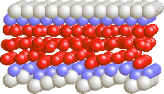
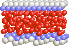
Simulation results for Vss=3, Vsl=1/3, lattice=12×11, Nl=1 to 5:
|
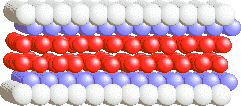
"soft" lubricant: Vll <<Vsl (Vll = 1/9)
|
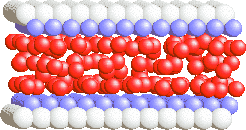
"hard" lubricant: Vll >> Vsl (Vll = 1)
|
|
|
|
|
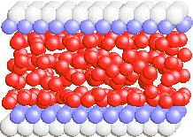
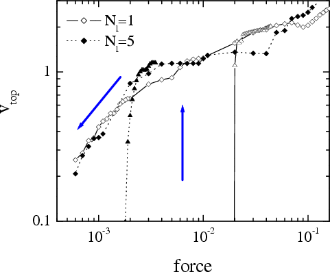
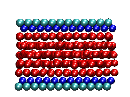
Nl=5 (enlarged view) |
Nl=1 & 5 (enlarged view) |
Simulation results for kspring= 3·10-4
|
Soft lubricant: Vll = 1/9
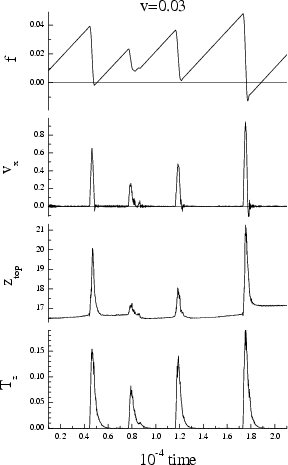
melting/freezing mechanism (vspring= 0.03)
|
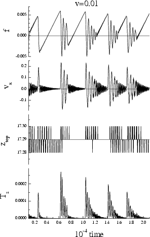
Hard lubricant: Vll = 1
(ideal structure)
inertia mechanism (vspring= 0.01)
|
 |
 |
| Nl=3 movie (avi 2 Mb) | Nl=3 movie (avi 1.6 Mb) |
The melting temperature Tm of a thin lubricant film confined between two solid surfaces is higher than the corresponding bulk value, because the confinement decreases the entropy of the film and shifts the bulk melting transition to higher temperatures.
 |
The melting temperature
Tm as a function of the number of lubricant
layers Nl for fload= 0.1. The solid curves describe the
fits |
The dependence Tm(Nl)
can be calculated analytically using the empirical Lindemann criterion: the
melting starts when the amplitude of mutual displacement of nearest neighboring
atoms reaches some threshold value of order 10% of the lattice constant. In the
case of a thin film, mutual displacements decrease for the confined film, where
the oscillations of the boundary atoms are suppressed. The mutual displacements
are maximal at the lubricant/substrate interface for the hard-lubricant case,
and at the middle of the soft-lubricant film where the internal interactions are
weaker than the interactions with the substrates. Therefore, in the
hard-lubricant system the melting starts at the interface, while in the
soft-lubricant case the melting starts in the middle of the lubricant.
Thus, a very thin confined film is typically in a solid state. This results in a
nonzero static frictional force fs.
The dynamics of the film is
significantly affected by the substrate, both in the solid and in the molten
phases. The solid phase, able to sustain shear stress, shows large diffusional
motions of the atoms; the molten phase shows a layered structure.
For more details, see O.M. Braun and M. Peyrard, Phys. Rev. E 68 (2003)
011506 "Dynamics and melting of a thin confined film"
(pdf files may be found here).
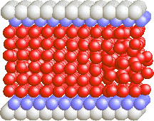
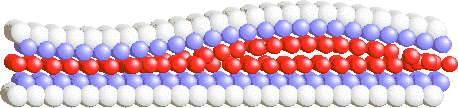
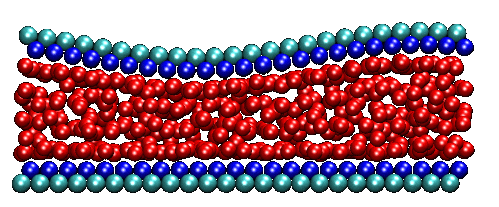
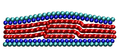
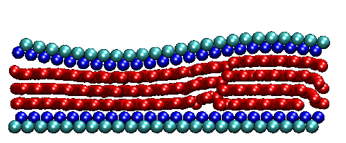
First, the soft lubricant freezes in a metastable configuration (which is different from stick to stick), where the two utmost lubricant layers are glued to the bottom and top substrates correspondingly and are characterized by a larger atomic concentration (e.g., for <10%) than the middle layers. The structure of the lubricant film has many defects (e.g., see two configurations below). The static threshold fs grows with the time of stationary contact (aging of the contact). Because the substrate-lubricant interaction (Vsl=1/3) is much larger than the interaction inside the lubricant (Vll=1/9), the sliding should begin somewhere within the lubricant, by depinning of the defects that stick the substrates.
|
Configurations of the Nl=5 lubricant just prior the beginning of sliding |
|
 |
 |
|
The annealed configuration at f = 0.087 |
The stick configuration obtained during stick-slip motion with vspring= 0.01 at f = 0.017 |
Second, there are two different steady-state sliding regimes, the "layer-over-layer sliding" (LoLS) regime, when the lubricant remains in the solid state, and the "liquid-sliding" (LS) regime, when the lubricant is melted due to sliding. These two regimes exist for different intervals of the driving force or velocity.
Third, the behavior of a very thin lubricant film with two or less atomic layers, differs qualitatively from the behavior of thicker films.
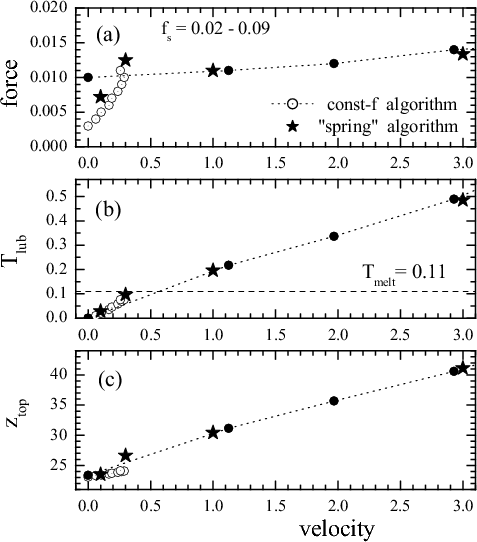 |
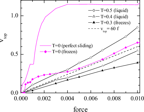
Figure soft5: (a) the kinetic frictional force, (b) the lubricant effective temperature, and (c) the thickness of the lubricant film as functions of the driving velocity for the Nl=5 system.
Stars show the data obtained with the spring algorithm, while circles and dash curves show the results obtained with the constant-force algorithm (open circles are for the layer-over-layer sliding regime, and solid circles are for the liquid-sliding regime). |
Layer-over-layer sliding. In the LoLS state the lubricant takes the well-defined layered structure; the utmost lubricant layers are glued to the corresponding substrates and move together with them, while the other (middle) layers slide (creep) one over another.
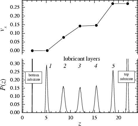 |
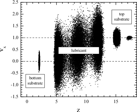
Figure soft7: Distribution of the x components of atomic
velocities across the film in the LoLS regime at f = 0.008;
see also the corresponding
movie (animated gif, 3 Mb). Bottom panel shows the distribution of atomic concentration across the lubricant.
|
The lubricant effective temperature grows with the velocity but remains lower than the melting one (Tmelt≈ 0.11 for the five-layer soft flat system). Therefore, the lubricant is in a "solid" state; however, there is exchange of atoms between different lubricant layers in this state. Due to atomic exchange, the 2D atomic concentrations in the layers may vary during sliding and, when two adjacent layers occur to have close concentrations, they become commensurate, lock together and move with the same velocity, while the main sliding occurs at the most "incommensurate" interface (e.g., see Fig.soft7).
The layer-over-layer sliding is stable for the velocities 0.05 < vtop< 0.3 and forces 0.003 < f < 0.011 (for the five-layer film at fload= 0.1; these intervals of velocities/forces shift to higher values as the load increases or Nl decreases). The system locks at lower forces/velocities, while at larger ones the lubricant melts and the system goes to the liquid-sliding regime.
Liquid sliding. The LS regime appears with the increase of the driving velocity (vspring> 0.3) or force (f > 0.01 for Nl=5). At lower values of the forces/velocities, e.g., for f = 0.011 and vtop< 1 or ~1, the system exhibits smooth sliding with two utmost layers approximately ordered and glued to the corresponding substrates (the "glued" lubricant layer may exhibit a slow creep motion relative the substrate), while the middle layers are melted. When the force/velocity increases to f = 0.012 or vtop>> 0.3, the glued layers melt as well. In the LS regime the x-component of the atomic velocities exhibits a linear gradient across the melted film. The sliding heats the lubricant to a temperature larger than the melting one, so that the driving itself maintains the lubricant in the molten state.
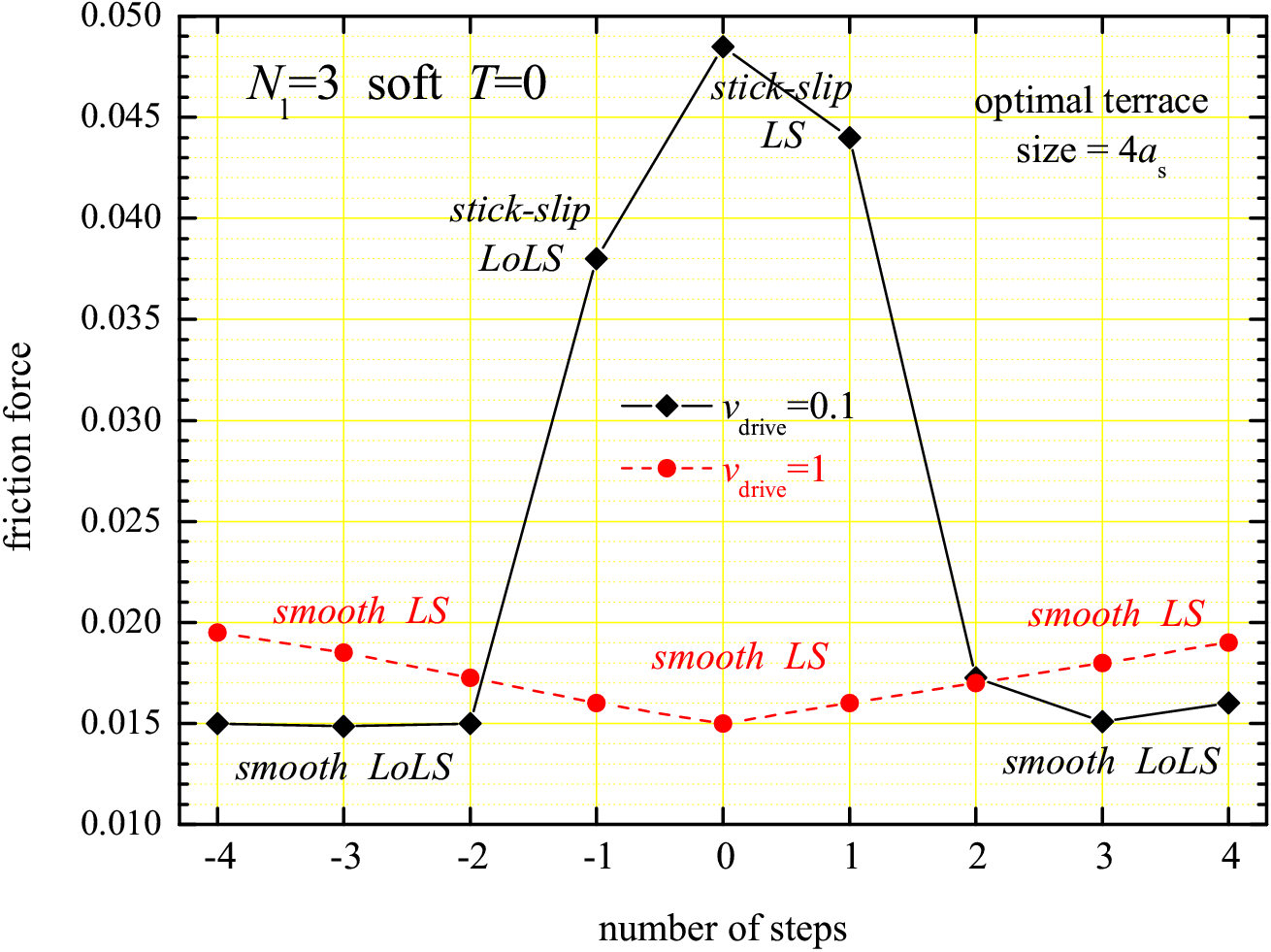
The transition from stick-slip to smooth sliding with the increase of driving velocity:
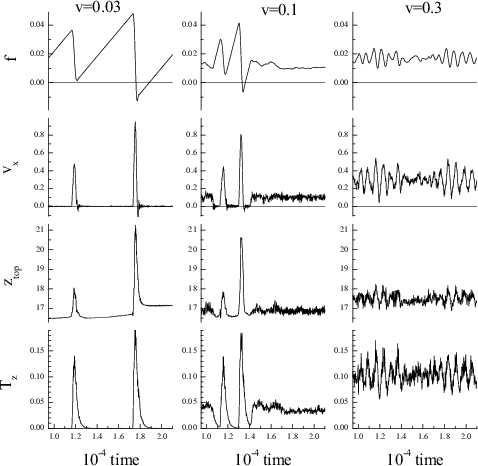 |
Figure soft26: Dynamics of the Nl=3 flat
system with the attached spring (kspring= 3×10
The top row shows the spring force, the second row shows the velocity of the top substrate, the third row shows the lubricant thickness, and the bottom row shows the effective lubricant temperature (note that Tmelt≈ 0.15 for the three-layer soft flat system).
The corresponding configurations are shown below (see also the dependences for the five-layer film) |
 |
 |
 |
|
stick configuration for stick-slip with vspring= 0.03 |
LoLS, smooth sliding at vspring= 0.3 |
LS, smooth sliding at vspring= 1 |
The threshold force fs as well as the system dynamics at the onset of sliding first of all depend on the starting configuration. Namely, if the starting configuration contains a small concentration of defects (dislocations) that pin the substrates so that fs only slightly exceeds the kinetic frictional force, then the interstitial defective atoms are pulled back into the lubricant layers, the lubricant film is ordered, and the sliding begins with the layer-over-layer mechanism. On the other hand, when the starting configuration is far from the ordered configuration (e.g., as the annealed configuration shown above), then at the onset of sliding the lubricant has to be reorganized by plastic deformation, its effective temperature grows above the melting one, and the lubricant film melts almost immediately with the beginning of sliding. See also an example (*.mov 12 Mb, needs QuickTime installed).
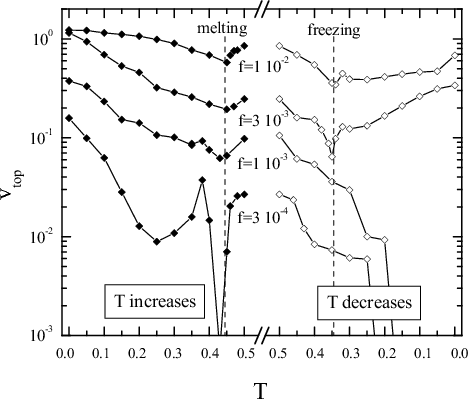
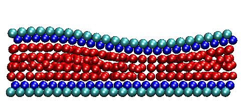
Two-layer lubricant film. Here, the two lubricant layers are glued each to the corresponding substrate, and the lubricant takes the two-layer crystalline structure at stick configurations (e.g., see the figure below). Because both layers are made of the same material, they are almost commensurate, thus the sliding should start from the breaking of bonds between these layers. For the two-layer soft flat system, the lubricant melts at Tmelt≈ 0.23 and freezes (when the temperature decreases) at Tfreeze≈ 0.19. Because the static threshold force is large for the two-layer system, at the onset of sliding the effective lubricant temperature increases well above Tmelt. Therefore, the sliding always corresponds to the LS regime, and the hysteresis, as well as stick-slip, occurs due to the melting-freezing mechanism. The film melts at slips, although it remains well layered in three layers (see typical configurations below).
|
|
|
|
stick configuration for stick-slip with vspring= 0.1 |
LS, smooth sliding at vspring= 1 |
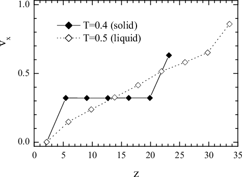
In the LS state, the bottom lubricant layer is almost glued to the immobile bottom substrate, moving with a very small average velocity corresponded to creep motion with respect the bottom substrate, the top lubricant layer in the same manner is almost glued to the top substrate, while the middle layer moves with the vtop/2 velocity (in average) as demonstrated in Fig.soft32 below.
|
|
Figure soft32: The x-component of atomic velocities vx versus z for all lubricant and substrate atoms in the smooth sliding regime for Nl=2 and vspring= 1. |
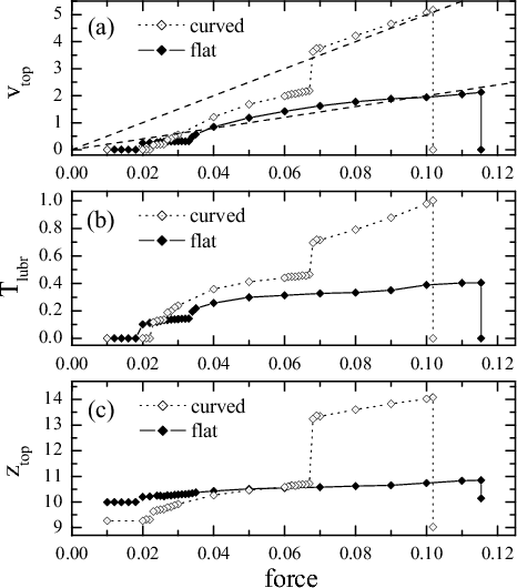
One-layer lubricant film. On the other hand, the Nl=1 system behaves essentially similar to the hard-lubricant system described below. Although the lubricant is heated due to sliding up to temperatures Tlubr~ 0.1 to 0.4, this temperature is still well below the melting temperature Tmelt≈ 0.57 of the one-layer film. Therefore, the hysteresis, as well as the stick-slip, exist due to inertia mechanism. Analyzing MD trajectories, at the onset of sliding we first observe the motion of two domain walls, which soon transform into a channel of moving lubricant atoms, and then to the "running" state of all lubricant atoms.
|
|
Figure soft37: (a) the velocity of the top substrate, (b) the effective lubricant temperature, and (c) its thickness as functions of the applied force for the one-layer lubricant film.
Solid symbols are for flat surfaces, and open symbols, for the curved geometry.
Indicate the huge hysteresis: when the driving grows, the sliding starts at f > 0.1, but the backward transition to the locked state, when the force decreases, occurs at f ~ 0.02 |
The same remains true for the case of the curved top substrate. In this case we observed at the onset of sliding a solitonic mechanism, which operates in the narrow region due to a bump ahead of it, so that the concentration in the narrow region increases and becomes incommensurate with the substrates.
|
|
stick configuration of the Nl=1 lubricant with the curved geometry just prior the beginning of sliding at f = 0.102 < fs≈ 0.105 |
|
|
LoLS, smooth sliding at f = 0.06 when vtop= 1.99 |
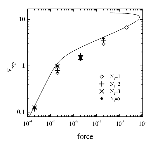
Flat surfaces and solid lubricant with an ideal crystalline structure: the universal dependence.
In the solid-sliding regime, when the top rigid substrate with one attached
s-layer moves as a whole with the average velocity
|
|
 |
The lubricant is heated due to driving.
The distributions of velocities in all cases can be well
approximated by Gaussian curves if we use different "temperatures" for
the lubricant and the s-atomic substrate layers as well as for different degrees
of freedom.
Definition: Ta = m‹(
vα–
‹vα›)2›,
where ‹...› is for the averaging over time and over
all atoms in a given layer, etc.
Simulation results (see figure to the right):
When one part of a system moves with respect to another part with a relative velocity v, then the rate at which work is done is equal to ε = vf, where f is the total force acting on the former. This may be used to define the energy losses of a given atom as
|
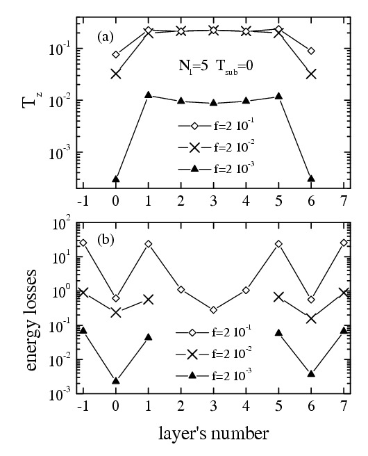
force-induced melting of the hard lubricant (Nl= 5, T = 0, f = ff ): movie for f = 0.5 >> ff (avi 1.6 Mb)
 |
The solid lubricant with the ideal structure provides the smallest frictional force (superlubricity). If the lubricant film is in a liquid state, the frictional force is much larger. When the lubricant is frozen again, it takes an amorphous structure because, due to the contact with the substrates, the energy is removed from the lubricant very fast, and the lubricant film has no time to order. The frictional force in the case of an amorphous lubricant is typically larger than for the molten one.
Ideal crystalline
configuration
(provides the
perfect sliding)
|
Configuration
after melting/freezing
(“amorphous”
lubricant)
|
 |
 |
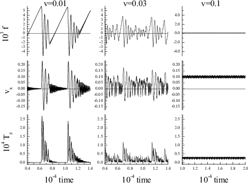 |
Perfect sliding: System dynamics for the Nl=3
hard system (kspring= 3·10 v=0.01 (stick-slip) → v=0.03 (irregular/chaotic) → v=0.1 (smooth perfect sliding) |
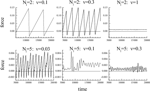 |
"Amorphous" lubricant: the frictional force vs time for three values of the spring velocity for Nl=2 and Nl=5 with flat geometry |
The results obtained with MD simulations, however, still remain on an empirical level. Being quite time consuming, MD provides the value of friction only for a given set of model parameters and hardly may explain general trends and laws, e.g., the dependence of friction on the temperature, sliding velocity, shape of lubricant molecules, parameters of the interaction between the lubricant and substrates, etc. The kinetic friction appears due to energy flow from the sliding interface into the bulk of substrates, which finally is to be converted to heat. The energy losses emerge mainly because of creation of phonons; the rate of this process depends on many factors, such as the density of phonon states, positions and velocities of the lubricant atoms relative the surfaces, which in turn depend on the sliding velocity, the heating of the interface due to sliding, etc. Below we outline a phenomenological approach which allows us to explain the simulation results presented above, as well as to predict the friction properties of similar systems without (or before) MD simulations.
The energy balance approach. The most natural way of fk calculation is through the energy balance arguments: the energy dEin/dt = Fvtop = Nsubfvtop pumped into the system per time unit due to external driving, must be equal to the energy dEdiss/dt dissipated in the substrates. The only way of energy dissipation in the model is through the viscous damping term mlη(z,v)v in Langevin equations of motion. When the lubricant has an effective temperature Tlub due to heating by the substrate as well as by the external driving, then its atoms move with a thermal velocity ‹vth›=(kBTlub/ml)1/2 ~ 0.3−- 0.7 at temperatures Tlub~ 0.1 − 0.5. When a lubricant atom is near a substrate at a distance zl from the nearest surface and moves with an average velocity vl with respect to it, then it losses per time unit the energy
|
(ph3) |
|
(ph4) |
|
(ph5) |
The first contribution in E1 comes from the x-motion, and the second one, from the motion along y and z. The last term in Eq.(ph5) describes the energy gain coming from the thermostat to mobile atoms due to action of the stochastic force; this contribution has to be subtracted from the frictional losses. In the thermodynamic equilibrium state the energy gain must be equal to the energy loss due to the thermostat, ε(0;Tsub). We assume that this contribution (from the stochastic force emerged due to the thermostat) remains the same in the nonequilibrium driven state. The factor s=2 in front of the r.h.s. of Eq.(ph4) appears in the case of symmetric sliding, where there are two sliding lubricant/substrate interfaces. In the asymmetric case, when there is only one sliding interface, one has to put s=1 and
|
(ph6) |
|
(ph7) |
|
(ph8) |
|
(ph9) |
Thus, we have to take into account two issues: first, the lubricant is always heated due to driving, and second, the lubricant structure depends on the sliding steady state, so that the kinetic friction force is determined by a rather delicate balance of these factors.
The geometrical factor. While the factor F in Eq.(ph7) increases with the driving velocity and temperature, the geometrical factors G and η1 decrease thus compensating the growth. First, the lubricant thickness d increases with the lubricant temperature due to thermal expansion. As a result, the distance of lubricant atoms from the nearest surface will increase with temperature too, e.g., as zl ≈ zl0+ βzlTlub. The increase of zl will result in the decrease of the coefficient η1. Second, the geometrical factor G is directly proportional to N'at, i.e., to the number of atoms in the lubricant layer just adjoined to the substrate surface. If N'l is the effective number of layers in a given configuration, then N'at can be found from the conservation of the total number of atoms, N'atN'l= NatNl. For the perfect crystalline structure of the lubricant we have N'at= Nat. In the case of hard lubricant with "amorphous" structure Nl < N'l ≤ Nl+1 so that N'at< Nat, or N'at= αNNat, where αN< 1. The case of liquid lubricant, when the lubricant structure is changed with the driving velocity and temperature, is more involved: the number of atoms that interact with the substrate, N'at, should decrease when the film thickness grows. For Tlub> Tmelt we found the dependence
|
(ph11) |
The lubricant temperature. The very important issue is that the lubricant temperature increases with the driving velocity. It can be found analytically with the help of energy balance arguments similarly to the approach used above: an energy R+ pumped into the lubricant (per atom and per time unit), must be equal to the dissipated energy R−. The energy flux from the lubricant to the substrates, which emerges due to the difference of their temperatures, may be defined as
|
(ph15) |
The pumped energy R+ emerges due to the "shaking" of the lubricant during sliding. This rate can be estimated with the help of linear response theory: Let the lubricant be perturbed by an oscillating force of an amplitude f0 and a frequency ω0. When one lubricant layer slides over another one with a relative velocity v0, it is disturbed with a "lubricant washboard frequency" ω0=2πv0/r, where r is an average interatomic distance in the lubricant. Then, the rate R+ can be found as
|
(ph16) |
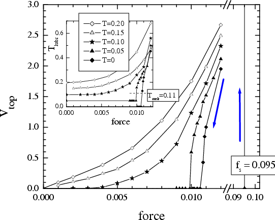
The perfect sliding.
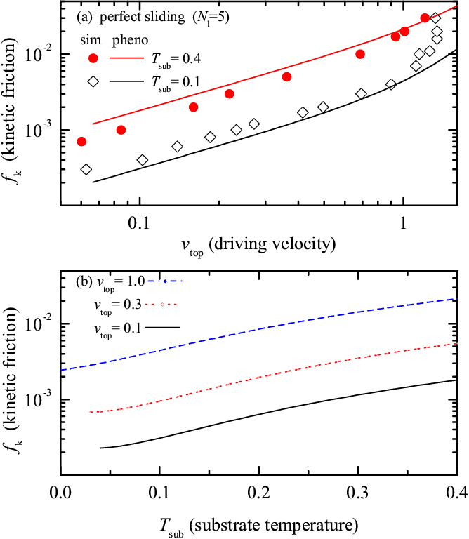 |
Figure ph12: Phenomenological dependences for the perfect sliding of
the Nl=5 solid lubricant for f0= 0.2.
The symbols correspond to simulation data. (a) Dependence of the kinetic friction force on the sliding velocity at Tsub= 0.1 (open diamonds) and Tsub= 0.4 (red solid circles). (b) Dependence of the kinetic friction on the substrate temperature for three values of the sliding velocity vtop= 0.1 (black), 0.3 (red), and 1 (blue). Here vlx= vtop/2, s=2, G=1.212, and from the simulation data we extracted other parameters: βz≈ 3.6, zl0≈ 5.21, βzl≈ 0.3, and zs≈ 2.12. Note that if we ignore all temperature dependences, we obtain in the Tsub= 0 case the "universal" dependence described above. |
The lubricant with the "amorphous" structure.
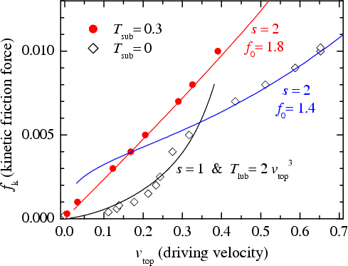 |
Figure ph13: Phenomenological dependences of the kinetic friction
force on the sliding velocity at Tsub= 0
(blue curve and open diamonds, the symbols correspond to simulation
data) and Tsub= 0.3
(red curve and solid circles) for the "amorphous" lubricant. Here αN= Nl /(Nl+1) ≈ 0.833 (simulation suggests αN≈ 0.81), and from the simulation data we extracted other parameters: βz≈ 2.33, zl0≈ 5.22, βzl≈ 0.333, and zs≈ 2.112. Note, however, that we had to take different values for the fitting parameter f0, namely, f0 = 1.4 for Tsub= 0 but f0= 1.8 for Tsub= 0.3. The T=0 movies can be found here (animated gif, 8.6 Mb). |
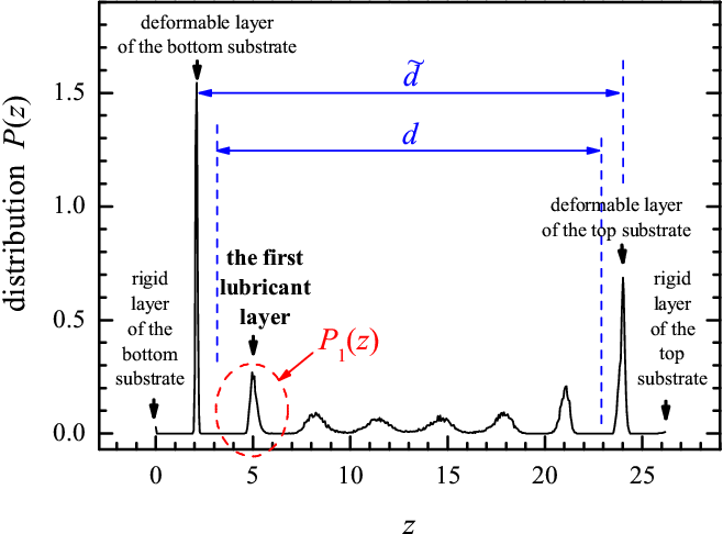
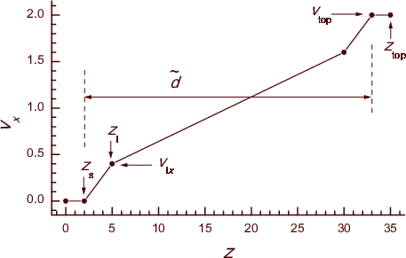
The LS (liquid sliding) regime. When the confined film is molten, its thickness changes with the temperature and driving velocity, and the factor G strongly decreases with temperature. To find N'at, we calculated the distribution of atomic concentration around the first lubricant layer P1(z) (see Fig.ph10) and then integrated it, N'at=C ∫ dz P1(z); the dependence N'at(Tlub) can be fitted with a good accuracy by Eq.(ph11). Then, we have to know the average velocity vlx of the first lubricant layer with respect to the substrate. Using the distribution of x-velocities across the lubricant obtained in simulation, we schematized it as shown in Fig.ph16. The dependence vx(z) is linear within the lubricant, but undergoes jumps at the substrate/lubricant interfaces. Using this picture, we assumed that vlx can be described by the expression
|
(ph20) |
 |
 |
|
Figure ph10: Distribution of atomic concentration across the lubricant in the liquid-sliding regime (schematically). |
Figure ph16: Schematic presentation of distribution of the x-velocity of lubricant atoms across the lubricant in the LS regime. |
In the result, we obtained the following dependences for the LS regime:
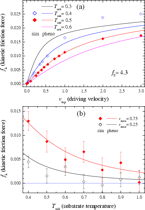 |
Figure ph18: Dependence of the kinetic friction force
(a) on the driving velocity at a fixed substrate temperature, T = 0.3 (black), 0.4 (blue), 0.5 (red), and 0.6 (magenta), and (b) on the substrate temperature at a fixed driving velocity vdrive= 0.75 (red) and 0.25 (black) for the LS regime. Symbols correspond to simulation data, while solid curves describe the phenomenological dependences. Here βz≈ 36.4, zs≈ 2.09, βN ≈ 2.84, Tmelt= 0.44, αN = 0.65, zl0= 5.41, βzl ≈ 0.313, and f0 ≈ 4.3. |
Discussion and conclusion. Thus, the simulation results can be satisfactorily explained with the help of the phenomenological approach. Almost all parameters that we extracted from simulation data, may in principle be calculated from first principles or estimated at least, except the two fitting parameters f0 and α. The first parameter, the coefficient f0 in Eq.(ph16), describes the amplitude of the oscillating ("shaking") force responsible for the sliding-induced heating of the lubricant. Note that the value of f0 correlates with the structure of the lubricant: the smallest value (f0= 0.2) was found for the perfect sliding regime, while much larger values (f0= 1.4 to 1.8), for the "amorphous" lubricant structure. The largest value (f0= 4.3) was obtained for the liquid lubricant. We could suggest that the value of f0 is proportional to "defectivity" of the lubricant film structure, although we have no clear understanding of this problem, and it requires further investigation. Second, the friction force in the LS regime strongly depends on the velocity of the first lubricant layer relatively to the substrate. According to Eq.(ph20), vlx is determined by the parameter α, i.e., by the gradient of x-velocity at the substrate/lubricant interface. This question is closely related to the "slip" or "no-slip" behavior of a liquid flow near a solid surface. The latter is characterized by the so-called slip length defined as
|
In turn, the slip length is determined by the liquid-surface interaction, i.e., either the surfaces are wetting or non-wetting by the lubricant (the latter situation corresponds to the hard-lubricant system described here).
Although the phenomenological theory presented above still uses some parameters, it allows us to explain the simulation results. In particular, it naturally explains the increase of kinetic friction with the driving velocity. Then, it explains the temperature dependence of the friction, which emerges due to interplay of two factors F and Gη1: the first factor increases with temperature, while the geometrical one, Gη1, decreases with T. Thus, the phenomenological theory allows us to predict, at least qualitatively, the behavior of other tribological systems in a general framework.
For more details of the phenomenological approach, see O.M. Braun, Phys. Scr. 78 (2008) 015802 "Phenomenological theory of kinetic friction for the solid lubricant film" (pdf files may be found here).
In the results presented above, the top and bottom substrates were identical. Now let us consider the tribosystem, where the substrates are not identical. In this case, the sliding becomes asymmetric, and essential changes of sliding mechanisms occur in the case of soft lubricants.
Note: magnitude of frictional forces, as well as the critical velocity vc, for the hard lubricant are in about ten times smaller, than for the soft lubricant.
low driving velocity: stick-slip motion |
high driving velocity: smooth sliding |
Nl=3 Vsl=1/3 |
 |
soft lubricant: Vll << Vsl
|
|
hard lubricant: Vll >> Vsl
|
||
| configurations / movies (mpeg) | ||
|
|
|
|
|
|
|
nsteps=3, smooth LoLS, vspring=0.1 |
nsteps=3, smooth LS, vspring=1 |
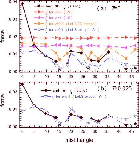 |
Figure rot14: Friction force as a function of the misfit angle φ (i.e., when the substrates are rotated one with respect to another on the angle φ).
Diamonds and solid curve describe the static friction, dotted curves show the kinetic friction force at different driving velocities (from v = 0.1 to 3) as indicated in legend.
Star symbols correspond to the regime of "solid sliding".
Panel (a) is for T = 0, and (b) is for the "room" temperature T = 0.025. |
As expected, in the LS regime (e.g., for v = 1 and 3 in Fig.rot14) the friction is almost independent of φ. However, the static friction, as well as the kinetic friction in the LoLS regime, may change on more than one order in magnitude, when the misfit angle varies. The highest friction is for φ=0. For all other angles studied, the sliding always corresponds to the LoLS regime at low driving velocities. Contrary to the φ=0 case, now the sliding is typically asymmetric, the sliding takes place at a single interface only, between the middle and one of the attached lubricant layers, i.e., the middle layers move either with the top or bottom substrate. The middle layers may remain ordered during sliding or, for other values of φ, they may be 2D melted (in the former case, the friction is lower).
For few special misfit angles, namely, for φ = 15.4, 27.2 and 42.8 indicated by stars in Fig.rot14, we observed the "superlubricity" characterized by a very low friction. In these cases, the lubricant film is solid and ordered during sliding, and moves together with one of the substrates. This is the "solid sliding" (SS) regime. However, the lubricant is not rigid during motion, which now corresponds to the "solitonic" mechanism.
Soft lubricant film (3 ≤ Nl ≤ 5):
for the static frictional force fs, Amontons law is explained by the interactions within the lubricant, that leads to μ ~ 0.5; the value of fs is determined by a particular structure of the frozen metastable lubricant film (i.e., by defects that should be broken at the sliding onset);
fs slowly grows with the time of stationary contact (up to in four times of magnitude) and reaches its maximum for the annealed configuration (aging of the contact);
the hysteresis of vtop(f) (when the driving force increases/decreases adiabatically) as well as the stick-slip motion at low driving velocities, is due to the melting-freezing mechanism; the transition from stick-slip to smooth sliding takes place at vc~ 0.1;
there are two steady-state sliding regimes, the LoLS sliding at low driving forces/velocities and the LS regime at larger ones. In the LoLS regime the sliding stops when the force/velocity decrease and v becomes lower than vtop~ 0.1; when the force/velocity increases, the lubricant melts and the LS regime begins to operate. The LoLS regime is more stable for narrower films, than for thicker ones;
at smooth sliding, the kinetic frictional force is approximately independent on the driving velocity, and is lower (or much lower) than the static frictional force. However, the lubricant effective temperature (the heating of the lubricant due to sliding) as well as the thickness of the film are proportional to the driving velocity;
for two-layer lubricant film, both its layers are glued to the corresponding substrates in the annealed and stick configurations, and the film structure is crystalline. As a result, the static frictional force is high, the lubricant always melts at the onset of sliding, so that only the LS regime operates. The hysteresis of vtop(f), as well as the stick-slip, always correspond to the melting-freezing mechanism, and the threshold velocity of the transition from stick-slip to the smooth sliding (vc~ 0.6) is also higher than for thicker films;
for one-layer lubricant film, the static friction is the largest, fs~ 0.1. The film typically is not melted during sliding, and the stick-slip motion is due to inertia mechanism similarly to the hard lubricant system (because of too high melting temperature of the one-layer film);
Perfect sliding (hard lubricant):
the solid lubricant film
with ideal crystalline structure provides the lowest frictional forces,
the kinetic frictional force depends on the sliding velocity v (Amonton’s laws does not operate for fkinetic);
the transition from stick-slip motion to smooth sliding occurs at vc~ 0.03 to 0.1;
Lubricant with amorphous structure (hard lubricant):
the solid lubricant film with
a metastable (amorphous) structure leads to a rather high frictional
forces,
the kinetic frictional force depends on v as fkinetic≈ Bv with B ~ 0.015 to 0.035;
the transition from stick-slip motion to smooth sliding occurs at vc~ 0.1 to 0.5;
Role of substrate temperature (hard lubricant):
if one starts from the perfect-sliding state, then the velocity decreases as T grows until the film melts. After that, the mobility grows with T, although it remains lower than the perfect-sliding value. For amorphous lubricant, the mobility increases with T ;
in the molten state, the kinetic frictional force is proportional to the sliding velocity v, e.g., as fkinetic≈ 0.017vtop;
fkinetic has peculiarities at T = Tm and T = Tfreeze, where the mobility slows down.
Last updated on November 26, 2009 by O.Braun. Copyright © by O.Braun.
Translated from LATEX by TTH, configurations produced by RasTop, movies – by VMD
