Microscopic Mechanism of the Transition from Stick-slip Motion to Smooth
Sliding: A Minimal Sliding Velocity
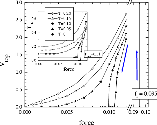
The smooth sliding regime is the
desired one for most devices. But what is a minimal velocity vc
when the sliding remains smooth? In what follows we show that at the nanoscale, vc
is of atomic-scale order, i.e. vc ~ 1 m/s
(for the stick-slip to smooth sliding transitions at the meso- and macro-scale,
see
 )
)
As
follows from simulation, the system always exhibits hysteresis
provided the lubricant is not molten, T < Tm: the
sliding starts at f = fs, but stops when the driving
force decreases below a threshold f = fb< fs,
when the sliding velocity is v = vb= v(fb) > 0. Therefore, if now one attaches a spring to the top substrate and the driving
velocity increases, one should observe the transition from stick-slip motion to smooth
sliding
similarly to that observed experimentally. In the simplest approach, if the free end of the
spring moves with a velocity vspring,
the motion will be smooth if vspring>
v(fb), while in the opposite case of
vspring<
v(fb) the stick-slip motion has to be
observed. A real picture is more involved, because
the shape of the function v(f) depends on the rate of f changing, and also fs depends on the timelife of
the
stationary contact.
The constant-force algorithm for the soft lubricant (Vll= 1/9)
with Nl=5:
vb~
0.3
The spring
algorithm for the soft lubricant (Vll=1/9) with
Nl=5
and kspring= 3·10–4: the stick-slip motion is
due to the melting-freezing mechanism, and 0.03 < vcrit <
0.1
The constant-force algorithm for the hard lubricant (Vll=1,
ideal structure of the lubricant film corresponded to the perfect sliding)
with Nl=1
or 5: vb~
0.2 to 0.3
The spring
algorithm for the hard lubricant (Vll=1, "amorphous" structure
of the lubricant) with Nl=2
and 5, and
kspring= 3·10–4: the stick-slip
motion is due to the inertia mechanism, and 0.1 < vcrit <
1
In all these cases the transition from stick-slip to smooth sliding occurs at
v ~ atomic scale, i.e.
v ~ 1 to 10 m/s, while
experiment typically shows the transition at driving velocities as low as
v ~ 1 μm/s (more
than six orders lower!). Thompson and Robbins (1990) suggested that the large mass of the
sliding block inhibits the freezing transition. However, the block as a whole
will never stop abruptly, but only the bottom surface of the block stops (Persson
1994). Below we prove this statement rigorously.
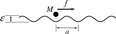 |
the rigid bottom substrate (external sinusoidal potential) +
one atom + the dc force is applied directly to the atom +
Langevin motion equation + underdamped external friction
|
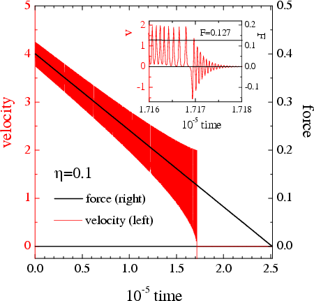 |
Figure: the velocity of the atom (red) versus time
when the force (solid line) smoothly decreases
|
The sliding-to-locked threshold force fb
can be found by balancing the gain in energy due to the driving force and the energy loss due to
dissipation. When the particle moves for the distance a (one period of
the external potential), it gains the energy Egain=
fa and losses some energy Eloss,
|
Eloss
= |
⌠
⌡ |
τ
0 |
dt ffric(t)
v(t) = |
⌠
⌡ |
τ
0 |
dt Mηv2(t)
= Mη |
⌠
⌡ |
a
0 |
dx v(x), |
|
(*) |
where τ is the "washboard period" (the time of motion
for the distance a) and ffric(t)=Mηv(t)
is the external frictional force that causes the energy losses. In the regime of
steady motion, these energies must be equal each other, Egain=
Eloss. Thus, the backward threshold
force for the transition from the sliding (running) motion to the locked (pinned) state is
determined by the equation
fb= min(Eloss)/a.
The minimal losses are achieved when the particle has zero velocity
on top of the total external potential
Vtot(x) = V(x) – fx.
In the limit η → 0 when f → 0,
analytics: From the energy conservation law,
(1/2)mv2 + (1/2)E [1
– cos(2πx/a)] =
E, we can find the particle velocity
v(x) and then substitute it into Eq.(*); this yields
| fb = |
Mη
a |
æ
è |
E
M |
ö
ø |
1/2
|
⌠
⌡ |
a
0 |
dx |
é
ë |
1 – cos |
æ
è |
2πx
a |
ö
ø |
ù
û |
1/2
|
= Cη(EM
)1/2, |
|
(**) |
where C ≡ (2π)–1∫02π
dy (1–cos y)1/2 = 2√2
/π ≈ 0.9. Equation (**)
can be rewritten as
fb= Mηv
= (2/π)Mηvm, where
v = a–1∫0a
dx v(x), and
vm= (2E/M)1/2 =
πv/2
is the maximum velocity achieved by the particle when it moves at the bottom of
the total external potential
Vtot(x).
The average particle velocity,
‹v›
= τ–1∫0τ
dt v(t) = a/τ, tends to
zero when
f → fb,
because
τ → ∞ in this limit. Thus, this simple
picture predicts that
fb < fs= 1, i.e.
the hysteresis exists due to inertia mechanism, but
vb~ M –1/2
depends on the mass of the sliding object.
|
Let the top substrate
consists of N "layers", the first (bottom) layer moves in the external
sinusoidal potential, and the dc force F is applied to the last
(top)
layer,
|
|
|
+
η |
|
+
η1 ( |
|
– |
|
) + g (x1
–x2) + sin x1
= 0, |
|
|
|
|
|
+
ηl
(2 |
|
– |
|
– |
|
) + g (2xl–xl–1–xl+1)
= 0, l = 2,...,N–1, |
|
|
|
|
|
+
ηN ( |
|
– |
|
) + g (xN
–xN–1)
– F = 0. |
|
|
|
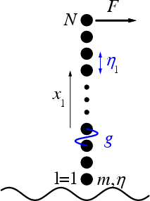 |
For the semi-infinite substrate we suppose that the damping ηl
inside the block is zero at the interface and increases smoothly far from the
interface,
| ηl
= ηm |
hl – h1
hN – h1 |
, hl =
tanh |
æ
è |
l – Ld
ΔL |
ö
ø |
, l = 1,...,N, |
|
|
where Ld = 0.6N, ΔL = N
/ 7 and
ηm= 10ωs.
Thus, a wave emerged at the interface due to sliding, will propagate inside the
substrate and will be damped there.
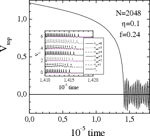 |
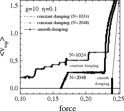
Figure: the transition from smooth sliding to the
locked state at the force f = 0.24 for the 1D top substrate of N = 2048
"layers" for g = 10 and η = 0.1.
Inset: the velocities of some selected layers of the top substrate.
One can see the wave emitted at the locking moment which propagates into
the substrate |
|
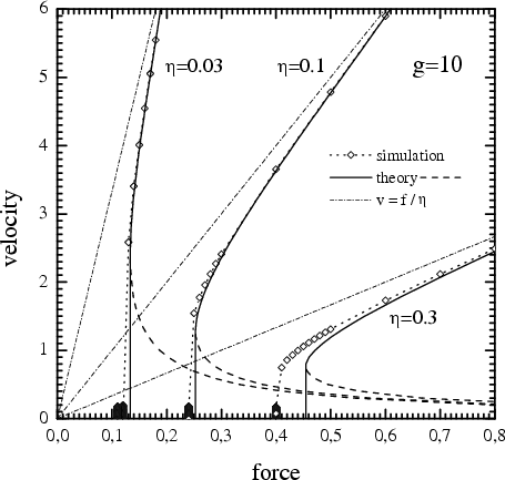 |
Figure 1D: v(f) for the 1D top
substrate with g = 10 for three values of the external damping
coefficient η = 0.03, 0.1 and 0.3. Open
diamonds and dotted curves show the simulation results (N = 2048).
One can see that for a semi-infinite substrate the sliding-to-locked
transition is sharp. Solid curves are for the approximate analytical
results (dashed curves, for the unstable branches), dash-dotted lines
describe the trivial contribution v = f/mη.
One can see a good agreement of approximate analytics (only the first
harmonic of ωwash
has been included) with simulation |
When the top block corresponds to a thin slab
(which may be glued to another large block so
that a reflecting
interface exists), then the wave emerged at the interface and propagated
through the substrate, will be reflected from the top surface of the
slab and go back, and a
standing wave
is excited. This wave does not allow the transition to the locked state,
so the sliding state persists now for much smaller values of the dc
force. This resonance effect depends on the width of the
top block — the narrower is the slab, the larger is
vtop
and for smaller forces the sliding persists.
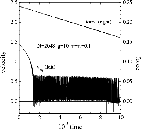 |
 |
| Figure: the transition from sliding to the locked
state as the force decreases with time for the 1D top substrate of
N = 2048 layers with the constant damping
ηl= 0.1 in the
substrate (g = 10, η
= 0.1) (enlarged view) |
Figure: the averaged velocity of the top substrate
versus the dc force for the 1D model with the constant damping
ηl= 0.1 in the top
substrate (g = 10, η = 0.1)
(enlarged view) |
A general approach: let us present the total
force as F = F1 + F2 + F3, where
F1 is the
force because of the
flux of energy into the top substrate, F1 = Eloss
/a, while the sum
F2+F3
= mηv
is due to the external damping of the atoms in the lowest (contact)
layer of the top substrate when it moves with respect to the bottom substrate,
and consists of
the "trivial" contribution F2 = mη‹v›
and the "fluctuating" contribution
|
F3
= |
mη
a |
|
⌠
⌡ |
τ
0 |
dt [v2(t)
– ‹v›2]
= |
mη
‹v› |
1
τ |
|
⌠
⌡ |
τ
0 |
dt [v(t)
– ‹v›]2. |
|
|
Then
we can use the following technique.
- The (top) substrate with internal
(excitable) degrees of freedom
is described by the causal (phonon) Green function
G(ω),
(ω2–iωηl–D)G(ω)
= 1,
where D
is the elastic matrix of the semi-infinite (top) substrate and
ηl describes
the damping inside the sliding block. Then the generalized susceptibility
is
α(ω) = –G(ω)/m
(here ω must be real).
- When the top block moves with
an average velocity
<v>, its atoms in the lowest layer oscillate with
the
washboard frequency
ω0 = (2π/a)<v>
+ higher harmonics.
-
Linear response theory: when a system is
excited by a small periodic force,
f(t) = Re f0 exp(iω0t)
(here f0 is real),
then its velocity will oscillate with the amplitude
v0=iω0x0,
where x0=α(ω0)f0
(let f0=fs).
- The rate of energy losses (the energy absorbed by the
top block per one time unit) is
| R = |
1
2 |
f02ω0
Im α(ω0) ,
or |
|
|
where ρ(ω) is the density of phonon modes in the top substrate ( ∫0∞
dω ρ(ω)
= 1 ),
- The energy absorbed by the top substrate during its motion for one
period of the external potential is equal to
Eloss(1)
=Rτ =2πR/ω0=Ra
/‹v›,
and the contribution F1 is F1=
Eloss(1)/a.
- If we take into account the lowest harmonic of the washboard frequency only,
v(t) =
‹v› +
|v0| cos(ω0t
+ φ), then
|v0|
= ω0|a(ω0)|
f0,
| F1= |
π
4 |
|
f02
m‹v› |
ρ(ω0) ,
and |
|
(F1) |
| F3= |
1
2 |
|
mη
‹v› |
|v0|2
= |
η f02
2m |
|
æ
è |
2π
a |
ö
ø |
2
|
|G(ω0)|2
‹v› |
|
|
Note that for a single atom, the backward threshold force is determined by
the F3 contribution
only. However, when the moving block has internal degrees of freedom, then F1> 0, and the backward velocity may be nonzero, so that
F2> 0 too.
- In a general case, one has to take into account all harmonics
ωn= (n+1)ω0,
n = 0,...,∞, and
perform the self-consistent calculation. Namely, for a given velocity
‹v› we have to start with
some approximate shape of x(t) [e.g., x(t)=‹v›t] and then calculate step by step:
- the force acting on the atoms of the top block,
| f(t) = – sin x(t) –
m η dx(t)/dt , |
|
|
- make its Fourier transform,
| fn = |
⌠
⌡ |
τ
0 |
dt eiωnt f(t) , |
|
|
- find the velocity in response to this force,
- then perform the backward Fourier transform,
| v(t) = (2π)–1ω0
|
∞
∑
n=0 |
e–iωnt
vn , |
|
|
-
and calculate x(t)
as the integral of v(t) over time; the output
trajectory must coincide with the input one;
-
finally, when
self-consistency has being achieved, calculate
|
F1
= – |
1
2m‹v› |
|
∞
∑
n=0 |
ωn
|fn|2
Im G(ωn)
= – |
π
am |
|
∞
∑
n=0 |
(n+1) |fn|2
Im G(ωn)
and |
|
|
| F3 = |
mη
2‹v› |
|
∞
∑
n=0 |
|vn|2
= |
πmη‹v›
a |
|
∞
∑
n=0 |
(n+1)2
|fnG(ωn)|2. |
|
|
(Only the first harmonic is taken into account in what follows). Let the top
substrate is modeled by the semi-infinite one-dimensional chain of atoms
oriented perpendicularly to the bottom substrate as in the simulation presented
above. The "substrate" atoms are coupled by
harmonic springs with the elastic constant g and the lattice constant
a; therefore the phonon spectrum of the substrate is ω(k)=ωmsin(ak/2), where ωm=2√(g/m), and the Green function is
| Im G(ω)
= – |
2
ωm2 |
|
æ
è |
ωm2
ω2 |
– 1 |
ö
ø |
1/2
|
|
|
(G) |
inside the phonon zone, |w| <
ωm, and Im G(ω)=0 outside the zone,
|ω| ≤
ωm. The real part of the
Green function is constant inside the zone, Re G(ω)=2/ωm2
for |ω| ≤
ωm, while outside the zone,
|ω| > ωm, the real part is equal to
| Re G(ω) = |
2
ωm2 |
|
é
ë |
1– |
æ
è |
x–1
x+1 |
ö
ø |
1/2
|
ù
û |
, |
|
|
where x = 2ω2/ωm2
– 1. The "surface" density of phonon states is equal to
| ρ(ω)
= |
4
πωm |
|
æ
è |
1 – |
ω2
ωm2 |
ö
ø |
1/2
|
, |ω|
≤ ωm. |
|
(rho) |
The substitution of this expression into Eq.(F1) yields
| F1 = |
1
4 |
æ
è |
2π
a |
ö
ø |
f02
g |
é
ë |
æ
è |
a
2π |
ö
ø |
2
|
4g
m‹v›2 |
– 1 |
ù
û |
1/2
|
|
(F1a) |
provided the washboard frequency is inside the phonon spectrum,
ω0< ωm.
In the low velocity limit, ‹v›→
0, Eq.(F1a) leads to F1
≈ f02/‹v›(mg)1/2.
Thus, the phonon contribution to the frictional force tends to infinity at
‹v›→ 0, because the
density of phonon states, Eq.(rho), is nonzero at ω=0 for the one-dimensional system. From Eq.(G) we have |v0| = 2f0/mωm and
| |G(ω0)|2
= |
4
ωm2ω02 |
= |
4
ωm2 |
æ
è |
a
2π |
ö
ø |
2
|
1
‹v›2 |
, |
|
|
so that the contribution F3 is equal to
|
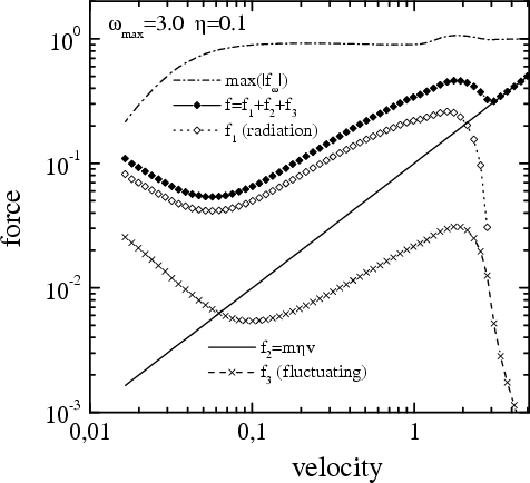
Figure: the frictional force (solid curve and solid diamonds) as a
function of the velocity of the 1D top substrate with g = 10 (ωm≈ 6.32) and η = 0.1, the contribution F1
due to radiation into the top substrate (dotted curve and open
diamonds), the trivial contribution F2= mηv
(solid line), and the fluctuating contribution F3
(dashed curve and crosses). |
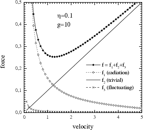 |
The function
f(v) has a minimum at
v = vb
where f(vb) = fb.
Thus, if the dc force applied to
the top substrate decreases, then
the transition from the sliding regime to the locked state takes place at
f = fb
when the average velocity of the top block is nonzero, vb> 0.
The comparison of the analytical and
simulation results was presented above in Fig.1D.
One can see that the agreement is quite good (recall that in analytical approach
we took into account the lowest harmonic of the washboard frequency only).
Emphasize also that the analytical approach corresponds to the
constant-velocity algorithm of MD simulation, while the numerical results were
obtained with the constant-force algorithm; both approaches lead to the same
result.
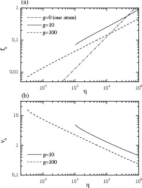
Figure: (a) the threshold force
fb and (b) the velocity vb for the sliding-to-locked transition as functions of the
external damping η in the 1D model
of the top substrate for two values of the substrate elastic
constant g = 10 (ωm≈ 6.32)
and g = 100 (ωm= 20).
The threshold values
do not depend on the total mass of the sliding (top) block, but do
depend on the elasticity of the block: a larger is
g, the lower are both threshold values
fb
and vb.
|
 |
Thus, the Green-function technique works
well for the 1D model and, therefore, it may be
applyed for the 3D model as well, where MD simulation (with few thousand of
substrate layers) is problematic.
For the semi-infinite 3D substrate
the Green function can be approximated by (Braun 1989)
|
Im G(ω) = – |
16
ωm6 |
ω (ωm2
– ω2)3/2
= – |
16
ωm2 |
ξ (1
–
ξ2)3/2, |
|
|
where
ξ =
ω/ωm,
|ξ| ≤ 1. The real
part of Green function may be found with the help of Kramers-Kronig relation,
|
Re G(ω) = |
2
π |
⌠
⌡ |
∞
0 |
dω1 |
ω1
ω12
– ω2 |
Im
G(ω1) =
|
32
πωm2 |
⌠
⌡ |
1
0 |
dy |
y2
(1– y2)3/2
(ω
/ωm)2
– y2 |
. |
|
|
The "surface" density of phonon
states is equal to
|
ρ(ω)
= |
32
πωm6 |
ω2(ωm2– ω2)3/2. |
|
|
The substitution of this expression
into Eq.(F1) yields
|
F1
= |
8 f02
mωm3 |
æ
è |
2π
a |
ö
ø |
2
|
æ
è |
1 – |
ω02
ωm2 |
ö
ø |
3/2
|
‹v›. |
|
|
In the limit
‹v›→ 0 we obtain
|
|v0|
= |
6 f0
mωm2 |
|
æ
è |
2π
a |
ö
ø |
‹v› and
F3 = |
18 η f02
mωm4 |
æ
è |
2π
a |
ö
ø |
2
|
‹v›. |
|
|
Thus, in the approximation when only
the main harmonic of the washboard frequency is taken into account, in the limit
‹v›→ 0 we obtain
F1=(8/ωm3)‹v›,
F2=η‹v›
and F3=(18η/ωm4)‹v›, which all together gives Fb= 0 and vb= 0.
However at low velocities of the top block, the motion of the atoms is highly anharmonic, and
the higher-order harmonics of the washboard frequency must be
taken into account. The self-consistent calculation leads to the results
presented in the figures below.
|
 |
 |
| The dependence F(v) and its
contributions for the 3D model of the top substrate (enlarged view). |
The dependence F(v) for the 3D
model for different model parameters (enlarged view). |
In all cases, the microscopic transition from stick-slip motion to smooth sliding
occurs at v ~ atomic scale, i.e.
v ~10 m/s, while “macroscopic” experiments
show the transition at spring velocities as low as
v ~1 μm/s (more than six
orders lower). A large mass of the sliding block
does not inhibit the freezing transition, because the block as a whole never
stop abruptly
– only the bottom surface of
the block stops. Thus, nothing in common: the experimentally observed
macroscopic smooth sliding corresponds in fact to the microscopic
(atomic-scale) stick-slip motion, while the experimental
(macroscopic) stick–slip motion is due to the fs(t)
dependence (aging of contacts). The corresponding
theory is similar to that used in earthquakes-like models.
Last updated on September 30, 2008 by Oleg Braun. Translated from
LATEX by
TTH