|
For
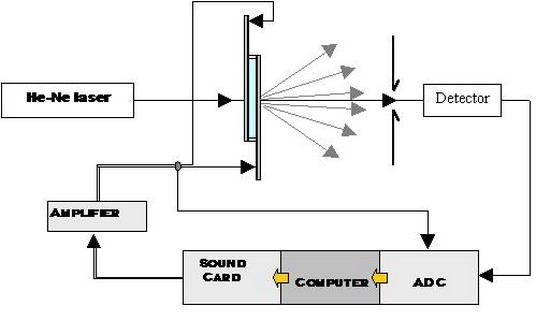
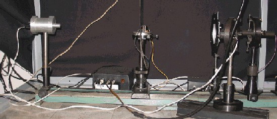
this purpose we use original home made set up. The
schematic diagram of the set-up is presented below. The computer is
programmed
so that at the output we have a signal with a given shape, amplitude
and
frequency (10…2000Hz). Usually, sinusoidal voltage is used.
The signal is
amplified using a wide-band amplifier. The active value of the voltage
applied
to the cell is controlled by a computer. The averaged transmittance
signal is
detected by a photodiode also connected to the computer. Except T-U
curves,
this setup allows to measure T-f and T-t curves. Both aligned LC cells
set
between two polarizers and scattering layers of LC composites can be
measured
by this setup.
|