Geometry: flat substrates and periodic boundary conditions parallel
to the surfaces
or curved substrate(s) to model an "open" contact (Persson 1989), when the z coordinate of the bottom rigid substrate is defined by
|
To have thermal equilibrium in a 3D model using Newton equations, one has to solve ~106 or more equations. Therefore, realistic simulation times are ~10τ0 or less, that is too small. Also, anyway the approach with solely Newton equations cannot include e-h damping (excitation of electron-hole pairs in the metal or semiconductor substrate).
Due to the driving force, energy is pumped into the system. This energy must finally be removed from the driven system. Indeed, the friction is due to energy losses. These energy losses are produced at the interface (but where – within the lubricant? in the utmost substrate layers? – see below simulation results), and then the energy must go out from the interface into the substrates, where it will be absorbed and transformed into excitation of internal degrees of freedom of the substrates (phonons, e-h pairs) and finally to heat which has to be removed from the system. Thus, we cannot use Newton equations – the external driving f will lead to T → ∞ finally – and we have to use Langevin equations with an external damping (but ηext= ?, and where does it operate? – see below).
A standard approach is to use Langevin equations for only few layers far from the interface. However, in simulation there always exists a competition "large system ↔ long times". Besides, the most important is a detailed modeling of the interface itself, so there are no reasons to include too many substrate layers far from the interface. Thus, it is reasonable to use Langevin equations for all lubricant and substrate atoms.
But what is ηext? If only the thermally equilibrium state is of interest, the value of ηext
is irrelevant (although the rate of approach to the equilibrium is maximal when
ηext~ ω0).
In 1D and 2D models, one typically uses
We use
|
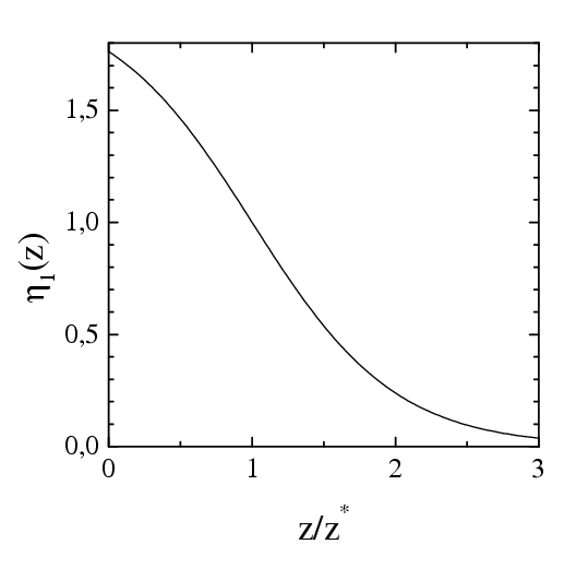
where η1(z) is trivial, η1(z) = 1– tanh [(z–z*)/z*], where z* is a parameter of the model (z*=2.12 in the simulation presented below) so that for the atoms in the s-layer, where z ≈ z*, we have η1≈ 1, while for the atoms in the first (closest to the substrate) lubricant layer we obtain η1~ 0.1
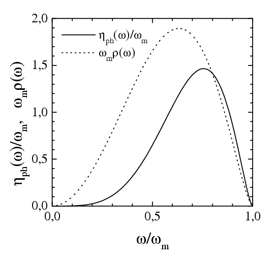
The phonon damping ηph(v): when an atom adsorbed on the crystal surface, vibrates with a frequency ω near its equilibrium position, the oscillation decays due to creation of phonons in the substrate with the rate (for references go here)
|
where the surface local density of phonon states may be described approximately by the function
|
and we took ωm=15 for the maximum (Debye) phonon frequency of the solid substrate.
Then we use ηph(v) = η(ωwash), where ωwash=2πv/a is the "washboard" frequency, and a=as for the motion along the substrate and a=z* for the motion in the z direction.
For the damping due to creation of electron-hole pairs in the metal or semiconductor substrate, we used ηeh= 0.01ωs= 0.049
| Dependence of the external damping on | |
| the coordinate z | the frequency ω = ωwash= 2πv/a |
 |
 |
Langevin equations with a velocity-dependent damping coefficient take a special form as described below. First, recall that a general form of the stochastic equation for a measurable variable q ≡ {ql} is the following,
|
(A1) |
|
|
|
(A2) |
|
|
In the case when the external damping does not depend on the velocity, we have ηR(x) = η(x), i.e., the standard expression. A deviation of ηR(ω) from η(ω) is essential at small frequencies/velocities for high temperatures only (T>0.5 for the parameters used in simulations).
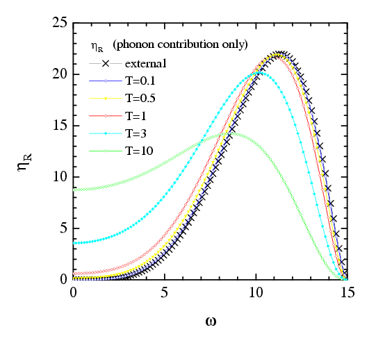 |
Figure: the coefficient ηR as a function of the frequency ω = 2πv/as at different temperatures |
|
(M1) |
|
(M2) |
|
(M3) |
|
(M4) |
|
(M5) |
|
(M6) |
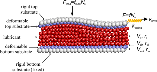
RS ≡ { XS,YS,ZS } is the center of mass coordinate of the S-th substrate (for the bottom substrate we took R1 ≡ 0).
fiα, S(ran) describes the random force acting on the i-th atom from the S-th substrate:
|
(M7) |
|
(M8) |
|
(M9) |
where MS=NSmS
is the mass of the rigid substrate, fext={f, 0,
fload} is the
external force applied to it, and
|
but the parameters are different for different kinds of atoms:
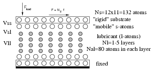
for the s-s interaction we took Vss= 3 = fixed (the maximal energy parameter, fixes the base energy parameter) and rss= 3 = fixed (the base length parameter),
for the l-l interaction rll= 4.14 (an "incommensurate" case),
for the s-l interaction, Vls= 1/3 (a "weak" substrate-lubricant interaction) and rls= 0.5(rss+ rll) = 3.57
Important: Vsl ↔ Vll !
either Vsl
<< Vll → solid lubricant
→ minimal fs and
ηeff
(e.g., Vll=1 for the "hard"
lubricant),
or Vsl >> Vll
→ commensurate →
melting/freezing mechanism of stick-slip (e.g., Vll= 1/9
for the "soft" lubricant).
Masses: ml=ms=mS=1
→ a typical frequency is
ωs= [Vss′′(rss)/ms]1/2 =
4.9, the typical period is τs= 2π/ωs= 1.28,
and the typical lubricant frequency is ωl= 2.05.
Typically the load was fload= –0.1
We use dimensionless unit ("natural units", n.u.). Connection with the SI system of units:
Let a real system is characterized by
Introduce the following coefficients:
Then for a typical system we have νe ~ νr ~ νm ~ 1, and
the unit of length 1 m = 1010 νr–1 n.u.,
the unit of mass 1 kg = 6·1024 νm–1 n.u.,
the unit of energy 1 J = 6.25·1018 νe–1 n.u.,
the unit of force 1 N = 6.25·108 (νr/νe) n.u.,
the unit of pressure 1 N/m2 = 6.25·10–12 (νr3/νe) n.u.,
the unit of time 1 s = 0.98·1013 (νe/νmνr2 )1/2 n.u.,
the unit of velocity 1 m/s = 1.02·10–3 (νm/νe)1/2 n.u.
For example, the load fload= –0.1 n.u. typically used in our simulation corresponds to the pressure P = –fload /as2 = 1.11·10–2 n.u. = 1.78·109 N/m2. To compare, the maximum pressure above which the plastic deformation begins, is
P ≈ 2·108 N/m2 for gold (a minimal value for metals),
P ≈ 109 N/m2 for steel, and
P ≈ 1011 N/m2 for diamond (the largest possible value).
Velocities: a typical value when the transition from a stick-slip motion to smooth sliding is observed experimentally, is vc ~ 1 μm/s = 10–9 n.u.
Last updated on April 1, 2004 by O.Braun. Translated from LATEX by TTH